Transformer Selection for Grid-Tied PV Systems
In this blog article, we’ll take up the important and sometimes confounding topic of transformer selection for PV and PV-plus-storage projects. We’ll establish straightforward naming conventions for transformers and consider the case of the step-down transformer for a grid-tied PV system. For this discussion, we’ll focus on low-voltage distribution transformers.
Windings: What’s in a name?
The “low-voltage side” is always secondary, right? Or is it that the “supply side” is always primary? Can you step up to a secondary side?
The language most of us often use to describe the winding configuration of a transformer is not always straightforward. This is, in part, because transformers have typically only been used for power flow in one direction, say, a 480 V utility line to service with 208 V loads. These naming conventions are no longer accurate with bi-directional transformers commonly used in solar PV and solar-plus-storage projects.
There is a simple approach to defining primary and secondary windings for PV systems, and it comes from the physics of energizing a transformer. A transformer is energized when an initial inrush of current propagates in either the inner or outer coils. With two-winding or bidirectional transformers, naming conventions mirror the order of energization. Which coil is energized first makes all the difference.


Because the inner coils are nearer to the transformer’s core, energizing the inner windings first induces a noticeably larger ampacity, which risks tripping overcurrent protection device(s). You steer clear of this risk when you energize the outer windings first and so the outer windings are typically energized first. For this reason, the outer windings are best called the primary, and the inner secondary.
…the outer windings are best called the primary, and the inner secondary.
In many step-down cases, the outer windings reside on the utility side. In those cases, the utility side is primary. As we’ll see in the example that follows, a common design for PV systems presents the need for a transformer that steps down to the primary coil.
Delta and Wye Configurations
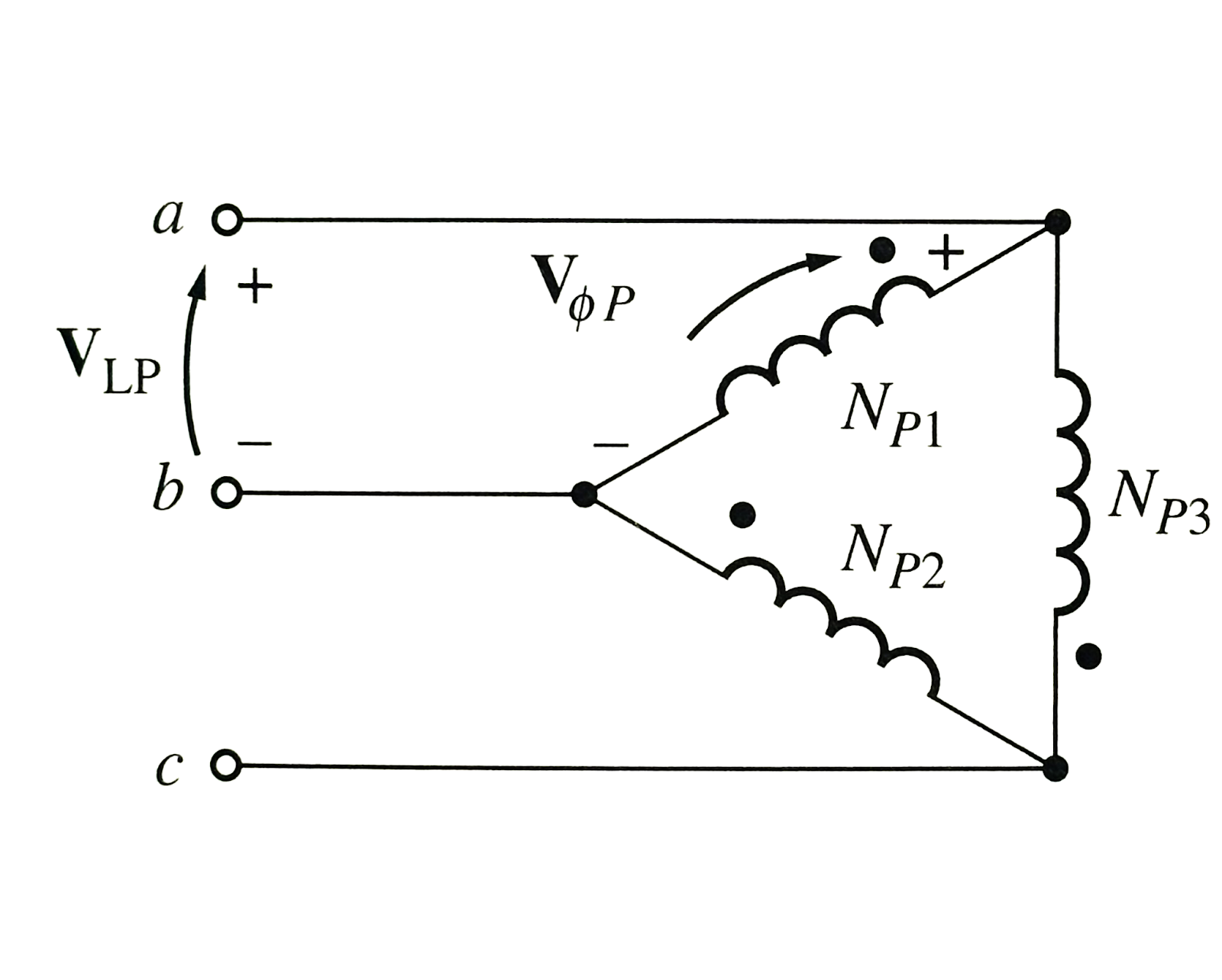
Delta and Wye windings receive their name from the general shape the phase coils take once connected. If the end of one phase winding meets the start of the next, and the second to the third similarly, the closed loop they form takes on a triangular or delta shape:
Courtesy of Chapman, 2002
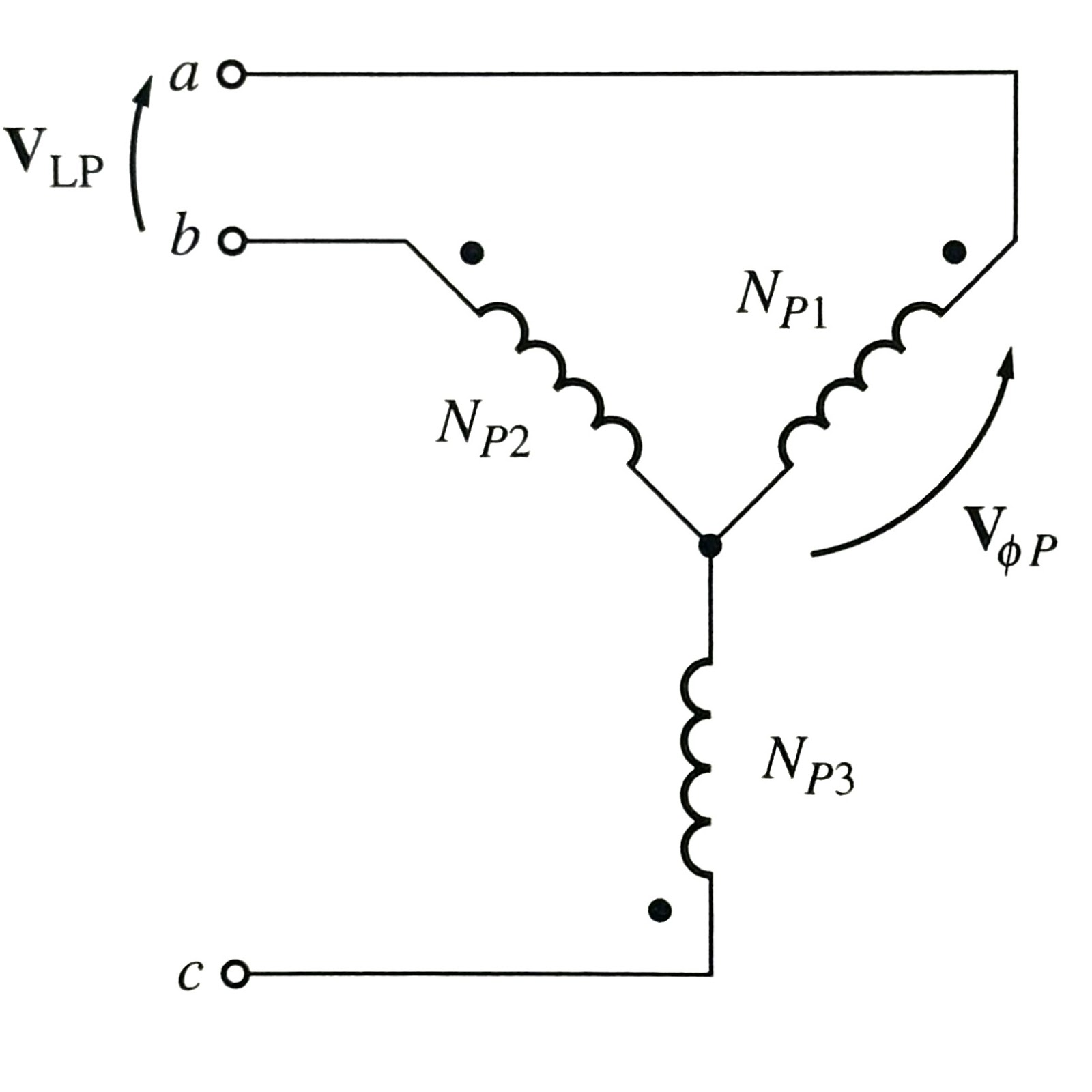
Whereas, connection configurations where an end of each phase winding is joined at a common node take on a y-like, or wye shape:
Courtesy of Chapman, 2002
There are advantages and disadvantages to both configurations. Oftentimes, the inverter and or energy storage system you’ve selected will have manufacturers’ requirements that determine your choice. Additionally, you must keep in mind any grounding requirements for the inverter side — a wye configuration is usually the choice to comply with these. Importantly, in grid-connected scenarios without storage, a wye with a neutral should be avoided on the transformer’s utility side. Such a choice runs the risk of circulating currents in the neutral, which, in turn, means more energy loss and overheating risk.
Delta connections are handy when higher phase-to-phase voltages and larger load efficiencies are required, like in industrial use cases. They are also useful if an unbalanced voltage distribution is desirable. However, a balanced voltage distribution is more often the goal, so delta may not be helpful. If a delta connection is used on both sides, there is a 30° voltage phase shift that must be accounted for, especially if multiple delta-delta transformers are synched in parallel. More on these considerations and others in the coming months.
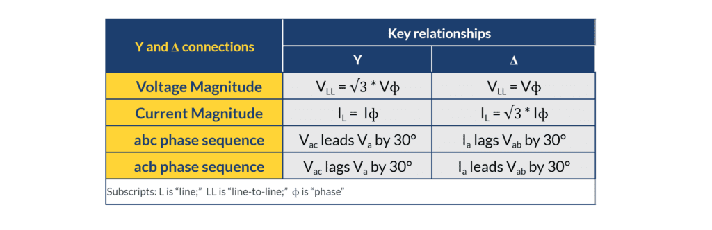
For reference, here are some voltage, current, and phase relationships for both connection types:
Exporting to the Grid
Before untangling more puzzling windings decisions for isolation transformers, transformers with energy storage in microgrid scenarios, or PV systems supplying both three-phase and single-phase dedicated loads, let us consider a common case: a grid-tied PV system without storage.
In this scenario, the PV system is exporting power to the grid. The transformer will need to accommodate, e.g. step down the voltage: from 480 V along the inverter circuit to provide 208 V to the utility side circuit.
In this context, the transformer will be energized first from the utility side, and the inverter side second. Given our newly gained naming conventions, this arrangement is straightforward. The utility side is primary and the PV side is secondary, despite the direction of current flow and the direction of the voltage step down suggesting otherwise.
The recommended winding choice for this grid-tied step-down transformer is a delta connection on the grid-tied/primary side and a wye with a ground connection on the inverter/secondary side.
This is typical for at least two reasons. First, choosing a wye with neutral winding on the transformer’s secondary side provides solid grounding and greatly reduces the likelihood that the inverter will face imbalanced phase-to-ground voltages. Indeed, some inverter manufacturers explicitly require a neutral connection to provide a proper reference for ground fault protection. Choosing an ungrounded delta connection on the inverter side introduces an inherent risk of imbalanced phases read by the inverter. Secondly, on the primary side, selecting a delta configuration avoids the risk of circulating current through the neutral of a wye with neutral. Such circulating currents in the neutral would pose a significant risk of transformer overheating, failure, or worse.
Designers, developers, and EPCs should always consult their relevant local and national electrical codes, the AHJ, and the transformer manufacturer when making any final specification decisions on a given project.
In future articles, our SMEs will dig deeper to tackle transformer selection for more involved solar-plus-storage system designs. Stay tuned by subscribing to our monthly newsletter.
Mayfield Renewables is a technical consultancy specializing in commercial and industrial PV and microgrid engineering. Contact us today for a consultation.