Technical Article
An Overview of Power Studies for PV Systems
As a solar professional, imagine your client telling you that safety and reliable operation are mission-critical for their system. How would you convince them that you can offer the best solution? True, the National Electric Code (NEC) is there to steer us away from many common pitfalls. But did you know that the NEC represents a set of baseline requirements? Just because a system is code-compliant does not necessarily mean it is functional. As useful and important as Code is, it can be a low-resolution yardstick when trying to answer certain types of questions.
For example, what happens when a fault in your client's system allows thousands of amps to flow from the utility to their system? What will happen to their equipment and electrical gear? Are they rated to handle this additional current without damage? Sure, the breakers you selected may meet Code requirements for overcurrent, but with a sufficiently extreme and sudden pulse of energy, they can fail or even explode before they’re able to safely interrupt the fault. If an issue does arise, are workers using the correct PPE?
Even when energy levels aren’t quite that high, are you sure that a ground fault will necessarily trip the PV breaker before the main service breaker? It would be a shame for your client’s entire business to unnecessarily go offline for an issue that could have been contained within the PV system itself. Unfortunately, this scenario can occur even when you’re paying attention to nameplate breaker ratings and following NEC to a tee. This is just one of countless questions that can be addressed using power studies to not only meet but exceed the baseline requirements set by Code.
What is a power study?
This umbrella term refers to an entire family of advanced engineering investigations of a power system, many of which can be performed using ETAP electrical modeling software. While these are not unique to the PV industry, they are an increasingly common part of the design process for commercial and utility-scale solar systems. In some cases, they may be required by Code. In others, they are called out in the NEC as an alternative way to meet certain safety requirements. In either case, they are a hidden gem for installers and developers, as they can reduce liability, boost stakeholder confidence, and at times even pay for themselves in O&M and materials cost savings.
The 2023 NEC includes many references to power studies, some of these include:
- 110.16 - Arc flash (1200 amps and greater)
- 110.24 - Fault current (all)
- 240.12 - Breaker coordination
- 700.32 - Emergency system breaker coordination
- 701.32 - Legally required system breaker coordination
- 706.15(C) - ESS fault current and arc flash
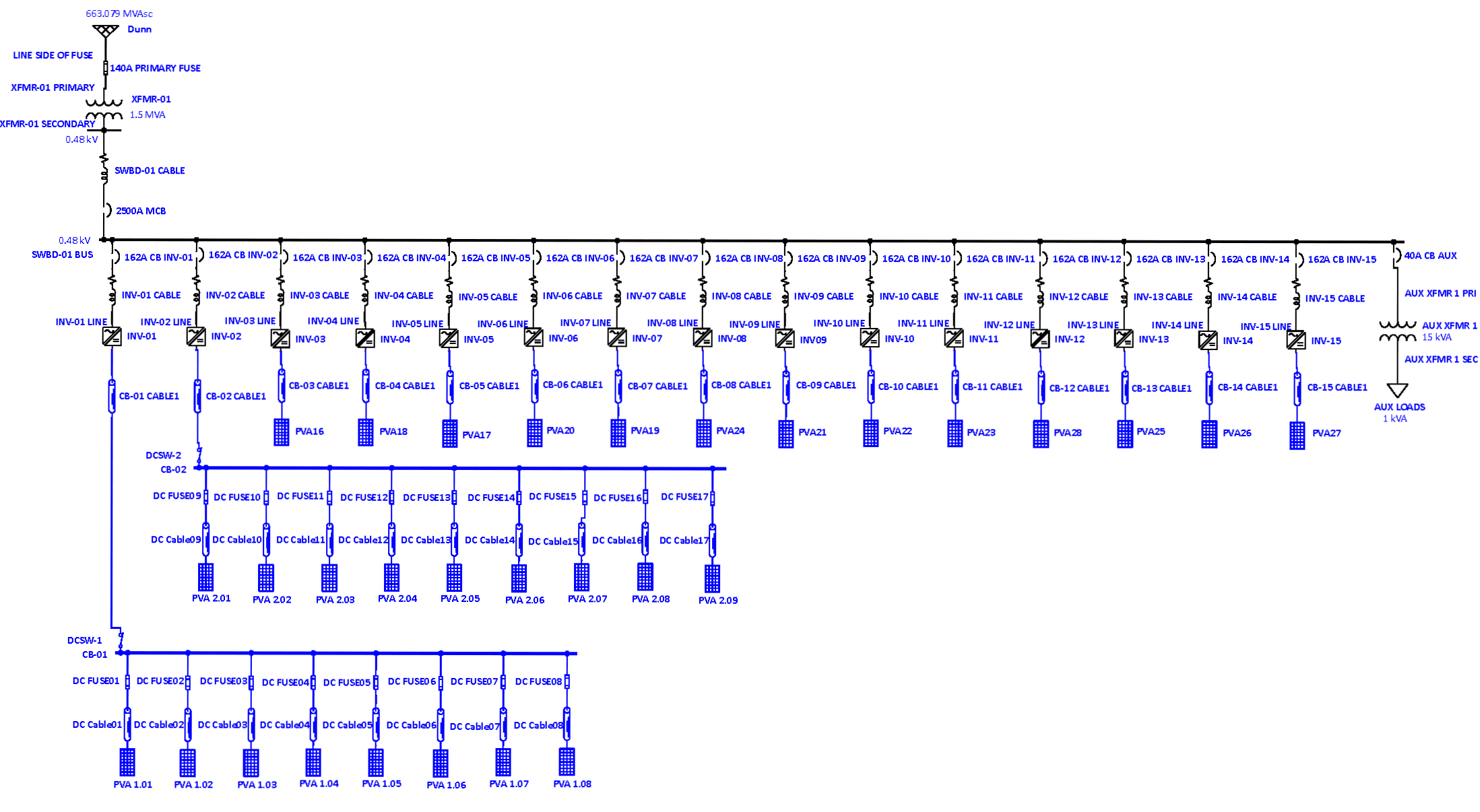
The conceptual basis of ETAP is a “digital twin” of your PV project–essentially, its virtual avatar within the software. Each piece of equipment can be selected from a vast built-in component library, which contains complete product specifications that define electrical operation. Once a digital twin is constructed, different scenarios are modeled to analyze how the system reacts under conditions that may be encountered in the real world.

What can be modeled?
A short-circuit study considers the impedance between electrical components within your system to calculate the amount of available fault current at all locations, no matter where a short circuit may arise. This analysis will allow you to select breakers and fuses with the appropriate Ampere Interrupting Capacity rating, ensuring safe fault interruption in the worst-case scenario. You and your client can rest easy knowing that no unexamined edge cases–even a catastrophic failure in the utility grid–will cause damage or fire in your circuits.
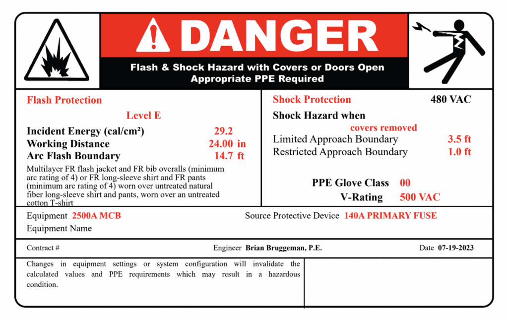
Worried about your technicians in the field, or about liability related to worker safety? An arc flash study will calculate the incident energy at each piece of equipment. The term “arc flash” refers to the thermal (heat) energy given off by an uncontrolled arc through open air. Arc flash hazard levels can be identified from the study, and proper protective equipment (PPE) requirements can be established. ETAP can even auto-generate arc flash warning labels like the example below, which are required by the 2023 NEC for commercial battery systems–and always recommended, regardless.
Beyond the NEC, OSHA also references arc flash hazards:
- OSHA 29 CFR 1910.132(d)(1) - Places arc flash safety responsibility on employers to evaluate the workplace for hazards and select and require the use of appropriate personal protective equipment (PPE) for its employees.
- OSHA 269 CRR 1910.269(l)(6) - Requires that workers be trained in potential electrical arc hazards and prohibits workers from wearing clothing that, in the event of an arc, could potentially increase the extent of injuries.
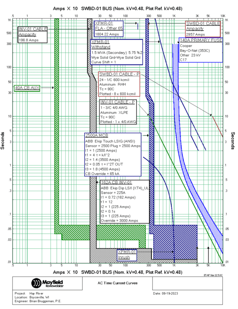
The hypothetical client in the example above, whose whole facility goes offline when a ground fault occurs, may benefit from a breaker coordination study. Even the quickest circuit breakers don’t trip instantaneously, and every OCPD’s behavior is characterized by its manufacturer in terms of a time-current curve as shown below. By coordinating the devices in your system based on these curves, you can derive the appropriate breaker trip settings. Making these subtle adjustments in the field can ensure that a fault in a small branch circuit will be caught locally before it propagates upward to trip a higher-level protection device.
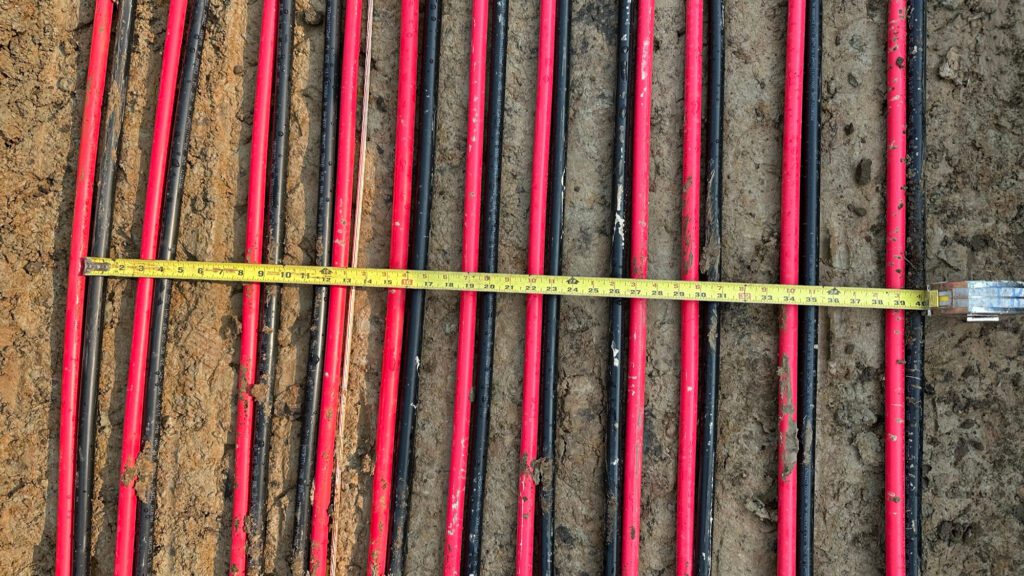
When it comes to trenched wire runs, underground cable thermal analysis can help you make optimal use of your resources. Trenching is expensive and intrusive, and unnecessarily large conductors are a waste of copper. Minimizing trench width and wire size can save time and money, as well as prevent unnecessary ecosystem disturbance. By modeling the temperature of underground power conductors based on ambient conditions, soil characteristics, and PV production estimates, you can determine the actual minimum sizing and spacing requirements that still keep your conductors below their thermal ratings. Compared to the cost of relying on the conservative default values provided by the NEC, investing in underground cable thermal analysis in the design phase can actually be cheaper in the end.
Many other useful studies can be performed on electrical systems, particularly when designing microgrids and energy storage systems. Other common studies include load flow analysis and system stability analysis. These are important in microgrid design to verify that the microgrid will be stable during normal operation and, crucially, during a fault. We will explain these analyses more in future blog posts.
Want to learn more about how these and other types of power studies can give your project the edge it needs? Mayfield Renewables is a technical consultancy specializing in commercial and industrial PV and microgrid engineering. Contact us today for a consultation.


