Technical Article
Ask Mayfield Anything: Expert Solutions to O&M Challenges
For August's Ask Mayfield Anything (AMA) episode, Ryan invited experts from different corners of the solar PV world to join the discussion:
- Dr. Ahmed El-Rasheed - Megger
- Ehab Elhanafy - Solis USA
- Jesse Waters - Tri-Force Energy
Together with Ryan, they take a look at many common operations & maintenance (O&M) challenges facing asset owners, EPCs, and testing professionals at present, and weigh in on how to best address some of them. As a starting point, the panel leaned on two helpful 2023 reports, Solargrade’s PV Health Report (from Heliovolta) and Top 10 Rooftop Safety Concerns (from Clean Energy Associates). These reports both reveal that many O&M challenges arise due to:
- Inconsistent protocols and lack of standards across our industry
- Insufficient training and knowledge associated with testing
- Cutting corners and shortcuts while testing in the field.
Here are some highlights from August’s AMA:
Challenge 1: Poor Termination
Poor terminations, often the result of cutting corners during installation, need to be screened for and fixed during commissioning. Ahmed recommends that both an insulation resistance test and a high-accuracy continuity test with a low-resistance digital ohmmeter (DLRO) be done before the first power-up. The goal is to establish an average low resistance value around the termination sites. For proper terminations, the average low resistance values should be in the milliohm (mΩ) range, so a standard DMM will not cut it.
Ehab advises that pre-commissioning checks ought to also include walkthroughs with visual inspection of terminal blocks and lugs to check for loose terminals, or torquing (mechanical) lugs to check for over-torquing, which can reduce circuit ampacity.


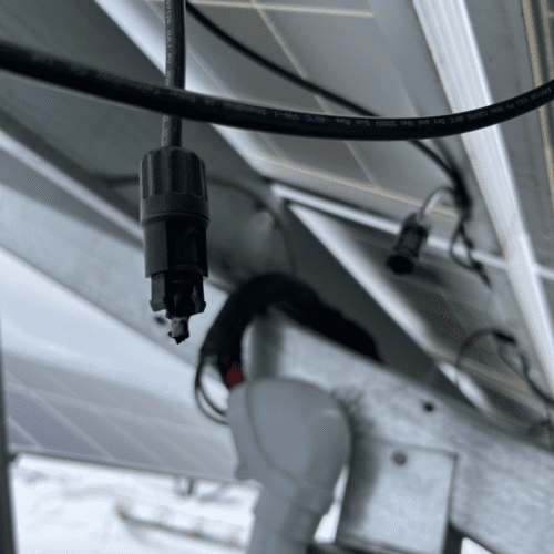
Challenge 2: Cutting Corners with Connectors
Ahmed recommends that, in principle, performing insulation resistance tests can assist with identifying poor connectors. An insulation resistance tester with a guard terminal will also measure the surface leakage current. More surface leakage current indicates a poor connection. Especially in damp environments, cross-threaded or loosely tightened connectors breed water intrusion dangers, like potential arc faults or ground faults. Ryan adds that wet insulation resistance testing is especially key to finding poor connections. But it may not always be possible or easy.
What are good strategies for dealing with conductors without sufficient slack? What about using spring-loaded connectors, or ferrules?
Jesse advises a drip loop and slack when possible since getting even basic operating measurements without slack can be difficult. On the other hand, gathering slack after the fact can be difficult depending on the size of the wiring box or other enclosures, and the system layout. Ryan comments on how common it is to see conductors pulled extremely taut and advises that slack remediation might best be evaluated on a case-by-case basis. If it causes more trouble elsewhere away from connection points, then it may not be a skillful choice.
Ehab prefers using compression (spring-loaded) lugs and ferrules when possible but warns that proper crimping tools and know-how are required if you’re going to use them. Some inverter manufacturers supply the needed hardware like Ferrules whenever applicable, so an installer doesn’t need to track down extraneous hardware. Some, not all, OEMs design their wiring boxes with enough room for service loops, and enough slack in mind.


Challenge 3: “Hot Spots”
After commissioning, during the O&M stage, it’s crucial to catch temperature abnormalities and address any developing problems early enough to avoid operation inefficiencies, failure, or possible damage. Modules can still perform surprisingly well despite damage.
A note of caution from Jesse is that damaged modules may not be detectable by a basic string-level test with a multimeter, which can show the modules are still operational and performing surprisingly well, despite the damage. This creates a potential safety hazard and requires the string to be shut down, and the damaged module(s) to be isolated and replaced.
Solder joint failures in PV modules lead to excessive heating and, in turn, cracked glass. These damaged PV cells essentially act as loads for all neighboring healthy cells. Bypass diodes are included to redirect current away from damaged or shaded cells, but damaged diodes can result in hot spots.
So then how do you prevent and monitor for hot spots?
Ahmed notes insulation resistance tests can track down hot spots, however, doing so on every single connector is laborious, unrealistic, and time ineffective. So taking a more macro-level test approach first to identify issues is smart.
Ryan concurs, asking “How many acres can you ask a field tech to walk to find a damaged module ?” For larger systems, the use of drones or other automated imaging devices might become time-effective and cost-effective, before sending a technician into the field.
Ehab encourages the use of thermal imaging tools to locate damaged modules and hot spots but warns that careful know-how in using the tool is a must. Certification for thermal imaging and reporting is highly recommended for those doing the testing.


Challenge 4: Damaged PV Module Replacement
Jesse cautions that finding like-for-like replacements for legacy module types is tricky. The success rate is about 2 out of 10 times with these older products (5+ years). The most important criteria for replacement modules, Jesse says, are a comparable short-circuit current rating and comparable mechanical dimensions. If the current rating and technical characteristics are a match but the mechanical dimensions are nearly perfect, you may have a solution, but likely have to swap the slightly ill-sized replacement module on the end of a string row with close attention to the attachment to racking.


Bonus Takeaways
- Proper bonding and grounding may seem low-priority, but they have important long-term O&M efficiency and safety consequences. Don’t overlook this in O&M.
- Consult module and MLPE manufacturers about proper insulation resistance test execution.
- Inverters can have integrated testing and fault support, consult your OEM.
- Annual tool calibration is a must.
To catch all the expert advice, watch this full AMA episode .
Looking for more O&M resources? Mayfield Renewables provides O&M training, both pre-recorded online and onsite in person. Contact us to start a project or learn more.


