
Technical Article
Best Practices in PV System Ground Fault Testing
Author’s note: A previous version of this article appeared in the September/October issue of North American Clean Energy.
Ground faults are common faults in PV systems. They manifest as an electrical connection between ground and one or more current-carrying conductors. Ground faults have many potential causes, but most are the result of improper installation or damaged components.
Ground-fault detection and interruption typically occur within the PV inverter, alerting the site owner to the fault’s presence. Locating the fault, however, can be challenging. This article will overview the tools and tests technicians can use to track down a ground fault in a PV array.
Ground Fault Electrical Concepts
In electrical systems, grounding establishes a stable electrical reference point, often called the ground potential. This reference point enables consistent measurement of voltage levels in the system. It also facilitates the proper functioning of electronic devices and protects against high-surge events from lightning and utilities.
Two primary types of grounding exist in PV arrays: system grounding and equipment grounding. To facilitate a low-resistance connection between all the materials, all PV systems should include an equipment grounding system that bonds all the metallic frames and components. If a ground fault occurs, the current from that fault therefore has a direct path to the PV inverter and to the ground-fault detector. Equipment bonding is a critical step in all PV installations.
Safety Considerations
When a ground-fault detector indicates a ground fault, unless extensive field testing shows otherwise, it is safe to assume that damage has occurred, repair is required, and there is an existing electrical hazard to the system. Technicians should proceed with utmost caution until they resolve the ground fault.
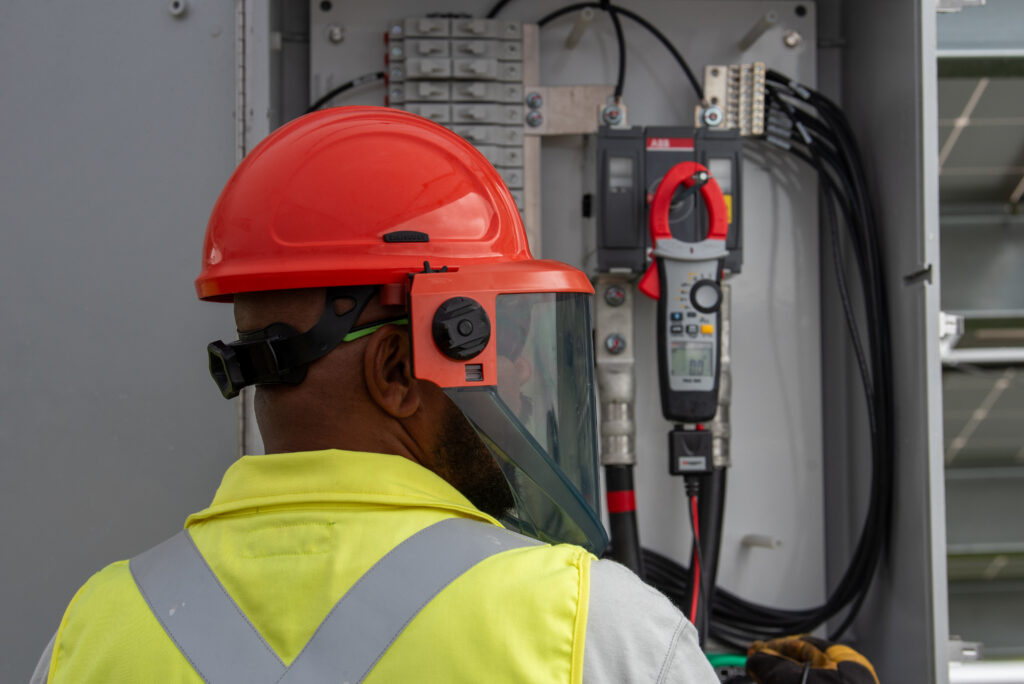
While the ground fault is active, it can energize the bonded metallic components that comprise the PV system. The risk of severe shock from direct contact with conductive components increases for high-voltage DC systems such as utility-scale PV arrays, which operate at 1,500 Vdc. Technicians must use the appropriate personal protective equipment (PPE) based on the hazards present. At a minimum, this will include high-voltage gloves, eye protection, and, potentially, arc-flash clothing.
The presence of a ground fault not only creates a safety hazard for technicians but also for the equipment within the array. High-energy fault currents can spark fires and melt conductors, which can cascade throughout the rest of the system. When the fault current exceeds what the equipment is rated to handle during normal operation, even small fault currents may be sufficient to damage the equipment.

Locating the Problem
To find the ground fault location, technicians must be comfortable performing various tests. To isolate the fault, best practice is generally to start at the inverter level, then segment the system to narrow the tests to the combiner and eventually to the string level. Performing the following tests helps identify fault locations.

- Visual Inspection: Damaged components causing a ground fault may be evident through a visual inspection. Taking the time to walk the site and visually inspect the system may provide a technician with a relatively quick identification of the problem.
- Voltage Measurements: Once the string conductors are safely isolated, voltage measurements can be recorded and compared. Using a digital multimeter (DMM), technicians should measure voltage from positive to negative, positive to ground, and negative to ground. The readings will return different values, which the technician can use in conjunction with the open-circuit voltage of each module to locate the ground fault. This process is well documented and outlined in a field testing guide published by NREL.
- Insulation Resistance Tests: If voltage measurements are inconclusive, insulation resistance tests can help locate a faulted circuit. A damaged conductor—from a weather event, long-term environmental exposure, or a hungry rodent—is among the most common causes of ground faults. An insulation resistance tester or high-range ohmmeter applies a DC voltage across the conductor under test, and injects a small current through it. The insulation resistance tester will then use Ohm’s Law to calculate the insulation resistance from the known voltage and current.

A good conductor will have very high resistance. Conversely, any conductor that is damaged, and in contact with a grounded object, will return a low resistance value. Below is a table of test voltages and minimum acceptable resistance values based on the system voltage as described by IEC 62446.

Among the most frustrating faults technicians may experience are intermittent ground faults. An inverter may detect an intermittent ground fault after a period of rainfall. When the technician visits the site and performs the above tests, however, no conclusive fault is located. When the inverter is reset, it operates without error.
A “wet insulation resistance test” is one way to track down the fault. As the name implies, the equipment is wetted with a water and surfactant (typically a detergent) solution. This process is outlined in IEC 62446 as one method used when necessary. The test requires careful segmentation of the array and methodical testing processes.
General Best Practices
Ground fault testing is not as simple as running a test and checking off results. Tracking down ground faults can be a tedious task. It involves an understanding of the output of several tests, along with some sleuthing and troubleshooting. Technicians must understand the safety risks, and use DMMs and insulation resistance testers to locate faults accurately and safely. The process must be approached methodically to avoid mistakes and time-consuming re-work. Ground fault testing is a critical and worthwhile process to ensure the ongoing safety and reliability of PV systems.
Looking for more resources on solar PV codes, standards, and O&M best practices? Mayfield Renewables offers educational workshops, in-field training for technicians, and project consulting services. Contact us to learn more.

