Technical Article
Code Corner: NEC Article 705.12(B)(3)(6) Load-Side Source Connections
In this edition of our Code Corner, we’re covering 2020 NEC Article 705.12(B)(3)(6) as it pertains to load-side source connections.
We begin this Code Corner by going to the end of section 705.12(B)(3). Here, the Code highlights the connections to the panels that have feed-through lugs. This is a common installation setup for systems that have meter mains. Meter mains may have feed-through lugs that feed another panel in the garage or elsewhere in a house or similar structure.
For the solar point of interconnection, it can be easier to land in that meter main, but the issue becomes complicated since we now have to account for the total current that can pass through the busbar, feeding the downstream feeder conductors and distribution panel.
In the 2020 NEC Article 705.12(B)(3)(6) we have the following language as a guide:
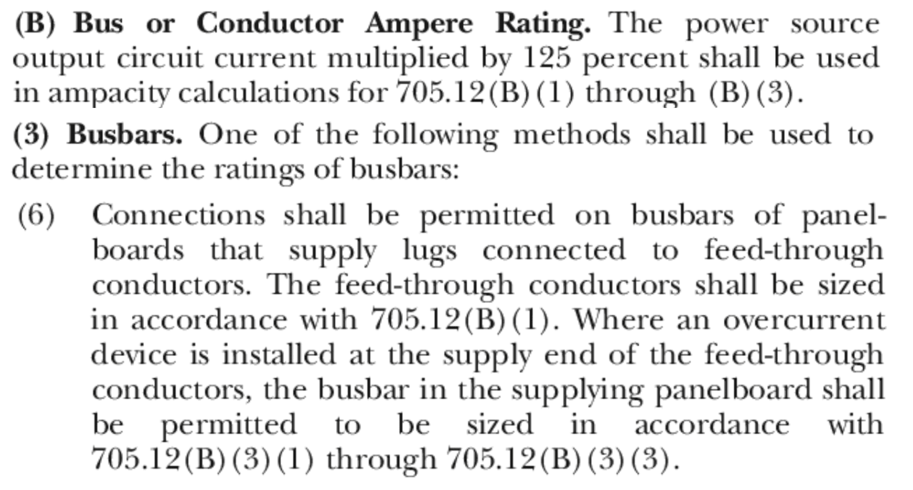
Toward the end of the section, we find the specific language that will help us here:
“Connections shall be permitted on the busbars of the panelboards that supply lugs connected to feed-through conductors.”
It’s important to recognize the Code references back to 705.12(B)(1) regarding connections to feeders. Then, the other part of the Code addresses when we are required to include an overcurrent device (OCPD) to protect the downstream conductors and panels (“at the supply end of the feed-through conductors”). In this scenario, we can use the “120% rule” in 705.12(B)(3)(2) for the panel board.
Below are a few images that show the scenarios discussed in the Code language for added clarity.
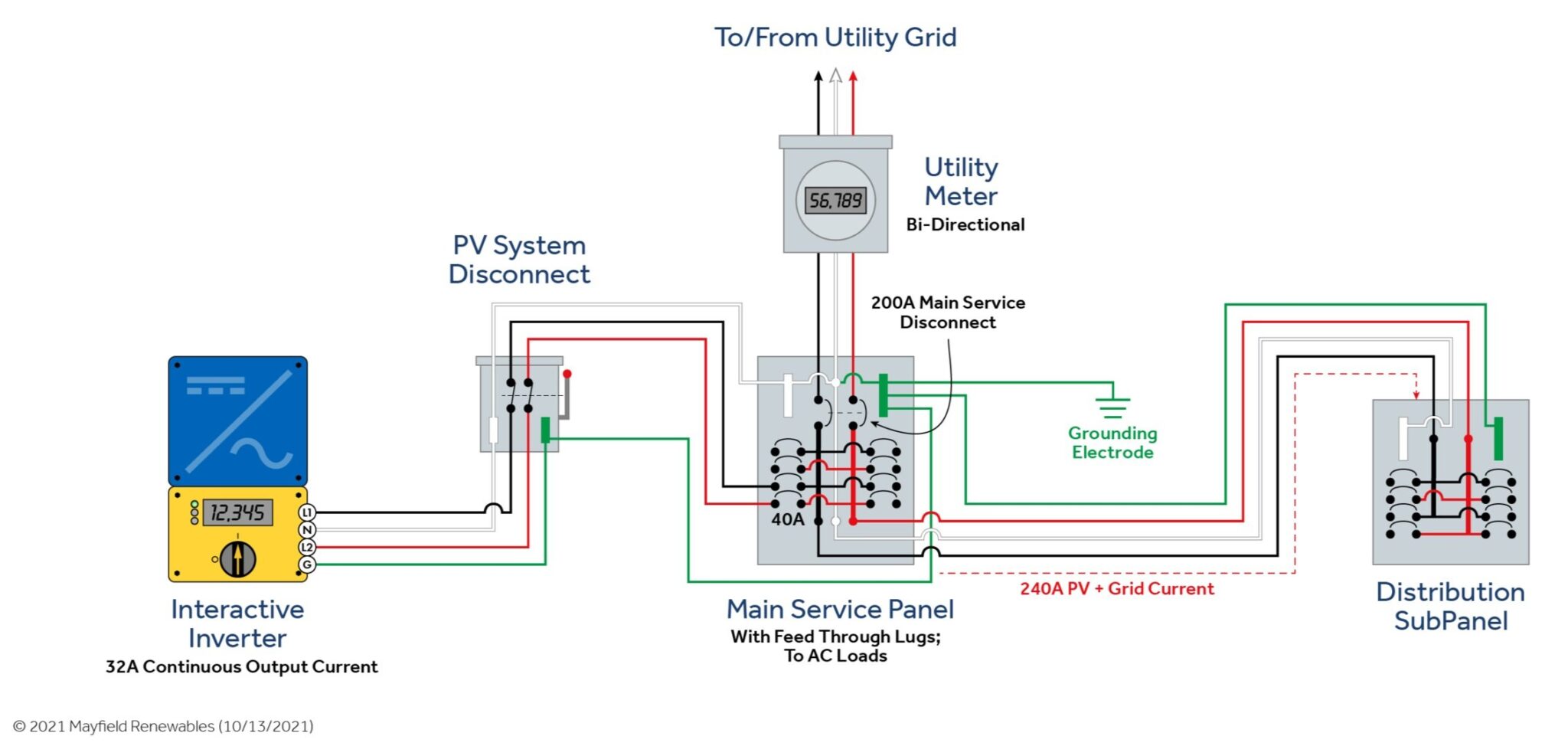
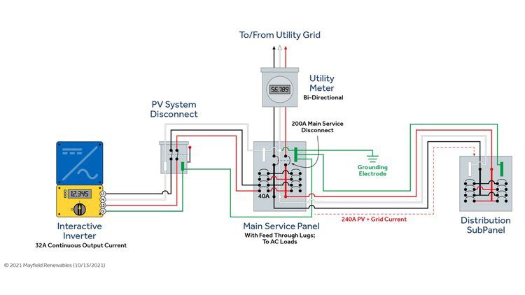
In the above instance, we have our main service panel right in the middle with the following:
- A 200 A main breaker
- A solar PV system entering the main service panel through a 40 A back-fed breaker
- Feed-through lugs that go to a main-lug-only panel that distributes additional loads in the system
We must be aware that when we make this connection with the 40 A breaker on the feed-through panel, we now have two sources of power feeding the busbars and the feeder conductors to the downstream panel. So, as shown in the image above, we would have 200 A from the utility and 40 A from the solar for a total of 240 A on the feeder through conductors and distribution subpanel.
Now, we must size the feeder and distribution panel appropriately. If we could upsize that conductor, then Article 705.12(B)(1) would allow us to do so, as long as the downstream distribution equipment is also rated for that ampacity. Of course, in most retrofit situations the feeder is only going to be rated for 200 A and upsizing that conductor can be next to impossible, or at least very costly and difficult.
Prior to the 2020 NEC code cycle, this scenario wasn’t discussed directly. Before, most installers would land the PV breaker on the main panel using the 120% rule with the breaker on the bottom of the main service panel and assume it was Code-compliant. However, upon considering that we have feed-through conductors and a distribution panel, we know that we are no longer in compliance—the back-fed PV breaker must be placed at the “opposite end” of the main OCPD in order to meet Code and safety standards.
To that point, by turning to 705.12(B)(3)(1) we now have the ability to include an additional OCPD to limit the amount of current on the feeder conductors from the feed-through lugs. This is a similar scenario to the feeder point of interconnections we have talked about in the past, where we have an overcurrent device on that conductor section.
The other part of the 705.12(B)(3)(6) section says that if you have this additional OCPD, then you can adhere to the point of interconnection rules of 705.12(B)(3)(1) through 705.12(B)(3)(3), which are simply different applications for where to put the back-fed breaker and how to size it. The most common being Article 705.12(B)(3)(2), often referred to as the “120% rule.”
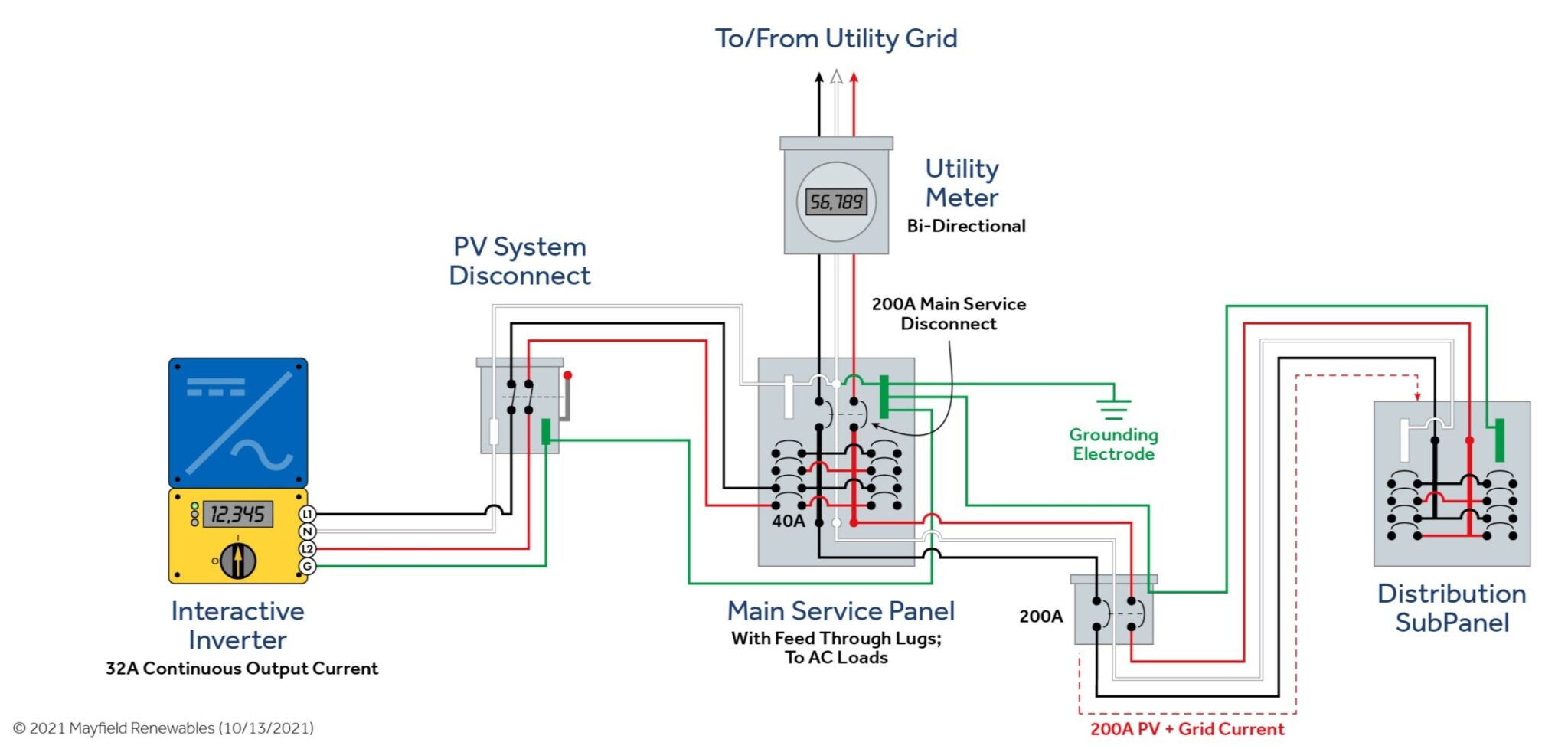
For added clarity, we’ll look at where the 200 A OCPD was added in the image above. If the new OCPD is close to the main service panel, then many inspectors would consider the OCPD to be “at the supply end of the feed-through conductors” and allow this type of installation. In the past, some installers may have looked at the distribution subpanel and thought, “it already has a main breaker” or “I can put in a main breaker” and the installation should be compliant by protecting the distribution panel from overcurrent. However, we really need to have that OCPD “at the supply end of the feed-through conductors.” To accomplish this, the OCPD must be placed near the main service panel to ensure the protection of everything downstream, including the feeders—not just the distribution subpanel.
This new Code language provides some additional clarity on where to put the OCPD by stating that it should be “at the supply end of the feed-through conductors.” Again, as mentioned in previous Code Corners, always talk to your AHJ before doing too much work. If the distribution subpanel in your project isn’t a long distance from your main service panel, you may be able to receive a waiver from the AHJ to bypass the existing Code requirements. Conversely, the AHJ may interpret this even more literally and require the OCPD to be in the main service panel precisely “at the supply end of the feed-through conductors.”
If you have questions on how to ensure your design complies with NEC 705.13(B)(3)(6), our System Design & Engineering team is happy to help. Contact us to start a project or learn more. You can also find more of our Code Corner videos on the Mayfield Renewables YouTube channel.


