SolarEdge Commercial PV Design Considerations
With the wide array of inverters on the market today, it’s important to stay up-to-date with equipment specifications when designing PV systems. In this article, we will cover commercial design considerations specifically for SolarEdge inverters with power optimizers (DC-to-DC converters). Often there is confusion around when and if series string fusing is needed in these systems. We have had to address this issue head-on and analyze the subject thoroughly, as we want our designs to be Code-compliant and safe, as well as being able to point directly to Code articles when challenged. In this blog, our focus will be on how many strings can operate in parallel together without the use of overcurrent protection devices (OCPDs) and how to calculate the minimum wire size required. Additionally, we will compare some alternative options which use OCPDs. These comparisons will cover issues we have identified and solutions we utilize when configuring a Code-compliant SolarEdge PV design.
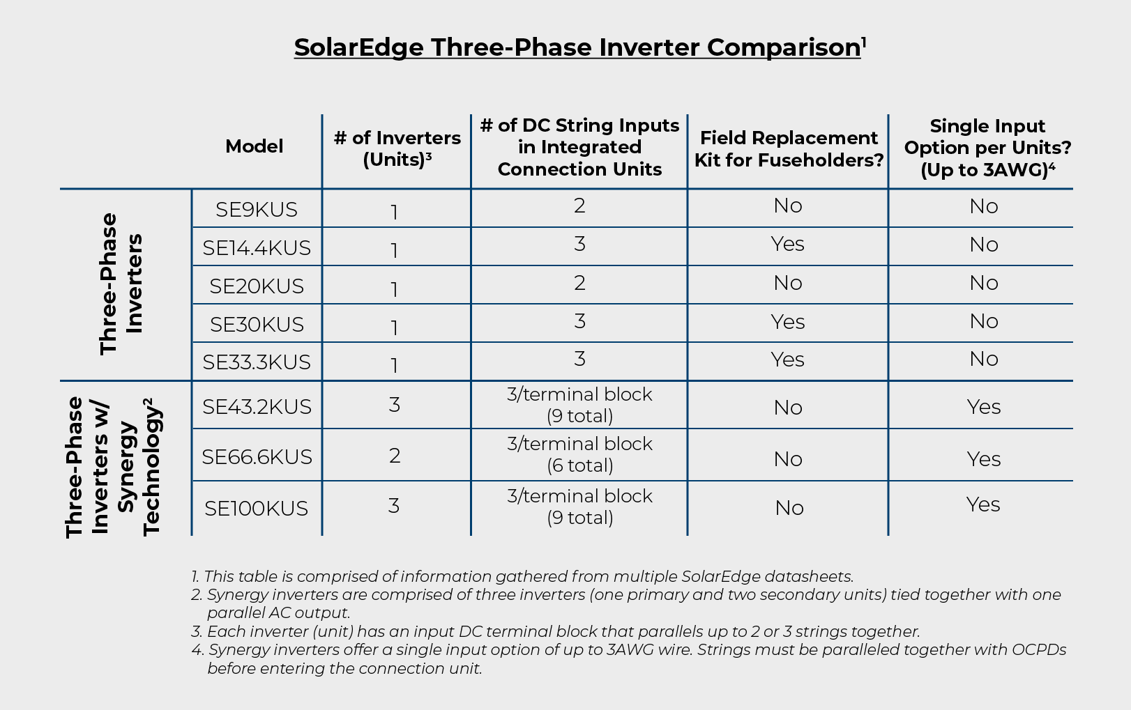
The maximum circuit current, along with the number of strings that will be paralleled together inside the inverter’s integrated connection unit, are significant values to pay attention to when configuring a SolarEdge PV design. Per the 2017 National Electrical Code (herein referenced as the NEC) section 690.8(A)(5), the maximum current for a DC-to-DC converter source circuit is the DC-to-DC converter’s continuous output current rating. For the sake of simplicity, we will focus this analysis on a commercial PV system utilizing a SolarEdge three-phase inverter with Synergy Technology, selected from the table below, paired with one of SolarEdge’s commercial-grade optimizers that has a maximum current rating of 18A: P800p, P850, and P860. Assume three strings per inverter unit.
In the PV industry to date, typical PV source circuits are sized to either 12AWG or 10AWG copper wire, depending on the maximum circuit current and any voltage drop considerations. The general rule of thumb is that systems with one or two strings per maximum power point tracker (MPPT) that comply with the NEC 690.9(A) Exception (2) (shown below) are exempt from needing any OCPDs, whereas systems with three strings per MPPT will typically need string fusing, as the maximum circuit current (calculated as the PV module’s short circuit current x 2 strings in parallel x 125%) x 125% will be greater than the module’s series fuse rating.
NEC Article 690.9 (A) Exception:
An overcurrent device shall not be required for PV modules or PV source circuit or dc-to-dc converters source circuit conductors sized in accordance with 690.8(B) where one of the following applies:
-
There are no external sources such as parallel-connected source circuits, batteries, or backfeed from inverters.
-
The short-circuit currents from all sources do not exceed the ampacity of the conductors and the maximum overcurrent protection device size rating specified for the PV module or dc-dc converter.
In order to apply Exception (2) when utilizing SolarEdge power optimizers with three strings, the DC-to-DC converter source circuit wire’s derated ampacity must be greater than the short-circuit current sum of 36A (combined maximum circuit current = 18A x 2 strings). Due to SolarEdge optimizers having zero backfeed current, the PV module’s conductors and fuse rating do not need to be considered when analyzing a DC-to-DC source circuit. For this exercise we will assume all terminals, wire, and connectors are rated for 90°C.
Option one: DC-to-DC Source Circuit fault scenario using 10AWG wire
In this scenario, we have two strings sending a combined current of 36A into the third string which has faulted to ground. Implementing the NEC Table 310.15(B)(3)(a) adjustment factor required for having more than three current-carrying conductors in a raceway, let’s assume six wires in a raceway and, for simplicity, we will ignore temperature derating. Six wires have an adjustment factor of 80%. 10AWG wire is rated for 40A at 90°C per NEC 310.15(B)(16) table. After applying this adjustment factor, 40A x 80% = 32A, which is less than the 36A short circuit current sum. This would be an undersized wire and an NEC Code violation without integrating OCPDs.
Option 2: DC-to-DC Source Circuit fault scenario using 8AWG wire
Utilizing the same scenario as Option 1, 8AWG wire is rated for 55A at 90°C. After applying the adjustment factor, 55A x 80% = 44A, which is greater than the 36A short-circuit current sum. This would be a correctly sized wire and a Code compliant installation without the use of OCPDs on the DC side.
While this wire sizing would be Code compliant, there are still a few additional factors to keep in mind. First, that the conductor’s ampacity will decrease even further once we apply the site’s ambient temperature correction factor, which may include a further temperature derate for rooftop raceways exposed to sunlight (depending on the Code cycle). Also, using 8AWG PV wire may require upsizing the conduit due to its larger outer diameter. In addition, MC4 connectors and a crimp tool will need to be rated for that wire gauge. Lastly, be aware of the space constraints within the connection unit. A direct correspondence with SolarEdge confirmed that (18) 8AWG PV wires (nine strings) will fit within the SE43.2KUS and SE100KUS inverter connection units.
Now that we have verified what the gauge of our Code-compliant wire will need to be in a three-string scenario without the use of OCPDs, we need to explore the alternative option of implementing OCPDs, which will allow for the use of 10AWG wire. Is this a cost-effective configuration for this commercial PV system?
Typically, the standard option would utilize DC combiner boxes, with or without an integrated disconnect. This option presents its own design considerations. Per NEC section 690.15, when the combined output of a DC combiner is greater than 30A “…an equipment disconnecting means shall be provided for isolation.” The disconnect needs to be integrated within the combiner box or within sight and within 10 feet of the equipment. By locating the box adjacent to the inverter with its integrated DC disconnect, a DC combiner without its own disconnecting means could be used. Since the SolarEdge Synergy inverters can have up to nine strings (three strings/unit), we would either need a DC combiner box that has three separate output channels or three separate single output combiner boxes. These options are viable at an increased cost in materials and installation but would need to be further compared to the cost of using 8AWG wire in larger conduit.
Alternatively, a less expensive option would be to utilize 1000VDC-rated MC4 in-line fuse holders with fuses, which, after a quick search, are priced online at $20.99 each. These are waterproof and have removable fuses. It would make sense to install them within a pull box or gutter directly below the inverter, ensuring the fuses are in close proximity to the inverter’s DC disconnect. This would allow for easy identification, safe troubleshooting, and servicing. This last configuration successfully accommodates for our number of strings per inverter unit and the maximum output current of the circuits, is Code compliant, and will come in at a reasonable cost. Therefore, this option is worth considering when weighing the choice between using OCPDs with smaller wire or upsizing the wire and eliminating the need for OCPDs.
In closing, we’ve found three viable options for our SolarEdge commercial PV designs. Site-specific details will further help determine which one is the most applicable choice. This is just one design aspect of many to pay attention to when designing a system with these products. The PV industry is fast-growing, where design requirements, solutions, and innovations are constantly needed and evolving. If you have any questions, comments, or ideas, please reach out and share.
References:
Brooks, B., PE. (2018, September 12). Protection of SolarEdge Power Optimizers [Letter]. Brooks Engineering, Vacaville, California.