Technical Article
PV Plan Sets 101
Over the last several years, due in part to generous federal (and in many places local) incentives, solar energy has become an increasingly popular choice with clients who want to offset their home or workplace energy demands. However, the process to go solar isn’t exactly cut-and-dried; there are many preliminary steps to be followed before a client can proceed to take advantage of this green energy source.
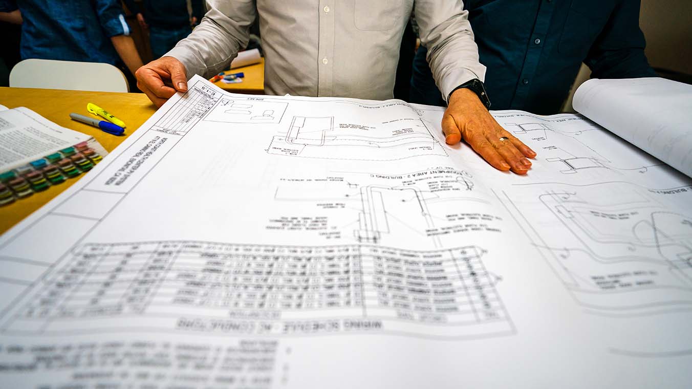
Working as one of many PV designers for Mayfield Renewables for the past eight years, I have ample experience with one of these preliminary steps: creating permit-ready drawing packages. These drawing packages, commonly referred to as “plan sets,” include all relevant structural, electrical and geographic information about a given solar project and are submitted to your local authority having jurisdiction (AHJ) for approval before the system can be permitted and built. In this article, I will provide some examples of how these permit packages are put together and what is typically included in these plan sets.
Whether you’re a residential homeowner looking at installing a 1-15kW system; a commercial building owner installing a 15-200kW system; or a corporation looking at your next big solar farm investment (1MW+), most of the same concepts will apply. Depending on the location and jurisdictional requirements of your home, building or land, the following concepts can be used and modified as needed to meet the permit office requirements.
Before we begin, if you would like to do some reading to get a thorough understanding of a PV permit package I would suggest taking a look at the “Expedited Permit Process for PV Systems.” This is a great place to start and will give you a general guide for your solar permit-ready drawings. With that said, let’s dive in.
At Mayfield Renewables, both our residential and commercial plan sets are broken out in fairly similar ways, plus or minus a few sheets that vary based on the complexity of the project. Design software is a crucial tool in creating these plan sets, regardless of system size, and there are many to choose from. Our team relies first and foremost on AutoCAD, which we supplement with other tools such as Helioscope--a web-based design software that remotely models a PV system using GIS and TMY data to output everything from shading and mismatch values to wire losses and overall system production estimates. We then use this modeling data to paint a picture for our clients of what levels of system production expect in the coming years.
Once we know our components and our system has been modeled, we begin the design process in AutoCAD. The end result is a plan set ranging in length from as few as five to six pages to as many as 100. Below is a brief description of what’s included in each sheet.
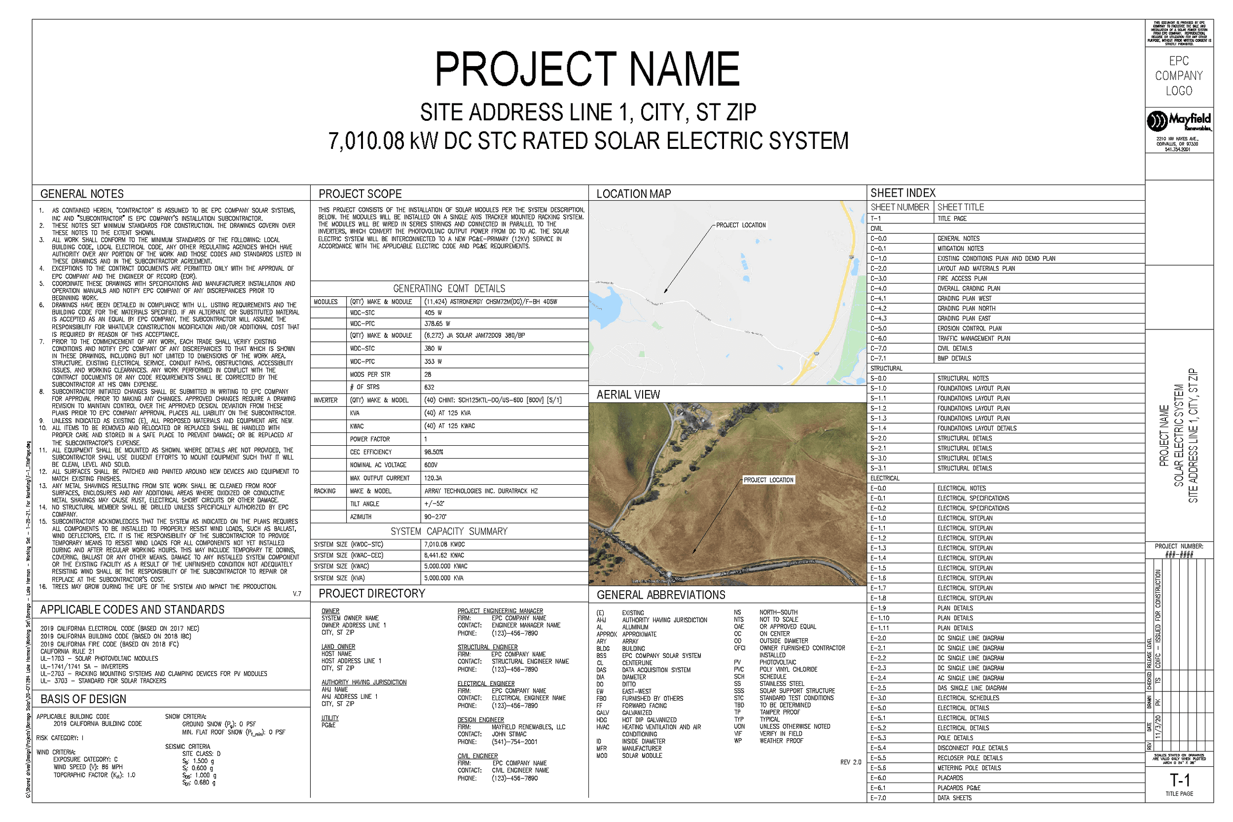
Title Page
The title page lists high-level information about the project such as the project name, location, scope of work (i.e., equipment being used), general notes about the project, and an index listing all pages represented throughout the plan set. Here, we provide as much information as possible to the building and permitting office so they can get a clear picture of what is being installed on site.
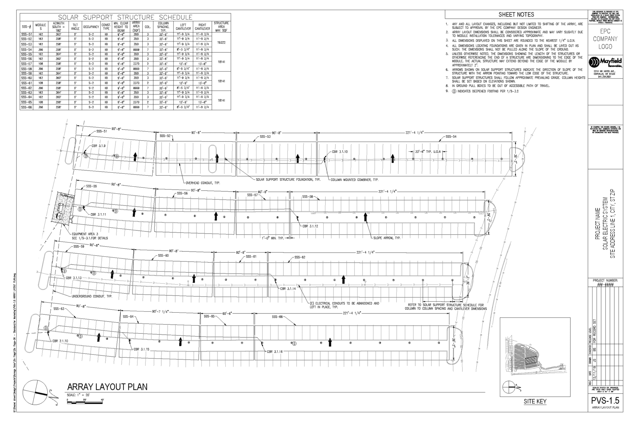
Overall Site Plan
The overall site plan is the first page with a clear image of where the solar array is located, whether that be on a rooftop, ground-mounted or atop a carport structure. This page consists of an overhead view of the property, including details like the property boundary lines; adjacent roads and properties (if applicable); solar equipment; where the proposed system will be installed; and any existing equipment on site such as a utility meter which would act as the tie-in point to the grid. All professionally submitted PV permit packages must include accurately scaled sheets, so obtaining all necessary on-site measurements is key to ensuring the site plan shows correct dimensions.
Roof Plan or Ground Plan
If your system is being constructed on a roof, this page will show a zoomed-in (to scale) drawing of your building with the correct location of your solar modules; mounting rails; rail attachments (spaced to engineering specifications); fire access locations (this varies for different building types and roof pitches); and any rooftop obstructions that could potentially impact the placement of your modules.
For ground-mounted arrays, much of the above will still apply, with a few additions. In this case, a detailed ground plan must show an accurate representation of the modules and mounting system, which includes concrete pads, pier posts and spacing between posts that should all be designed with the site geography and soil type(s) in mind. Every area, whether you live in California or New England, will have unique site-specific challenges to address when determining how many posts you need for the size of your system and how deep you will have to embed your piers. A structural engineering analysis may be required to determine this depending on the system complexity and local climate considerations such as snow load and wind uplift.
Structural Details
If required for a roof-mounted system, a structural page showing a roof section detail, attachment detail and some mechanical information depicts a clear representation of how the solar modules will attach to the roof-framing members and how the added load from the solar array will carry throughout the structure. In the information section, it is good practice to outline how many attachments are going to be used; manufacturers of the products you are using; and the weights of the modules, rails and attachments if structural calculations are required.
Electrical and Structural Notes
These pages overview how the system will be constructed, both electrically and structurally, and are designed to be a guide for the installer. For example, the electrical notes page may include details on wiring methods; safety signs and labels; disconnecting means; grounding; and ground-fault protection to ensure the system is built to meet safety standards set by the National Electrical Code. Applicable Codes will be cited on these sheets for general reference. Structural sheets follow the same format but reference the structural codes and best practices as required.
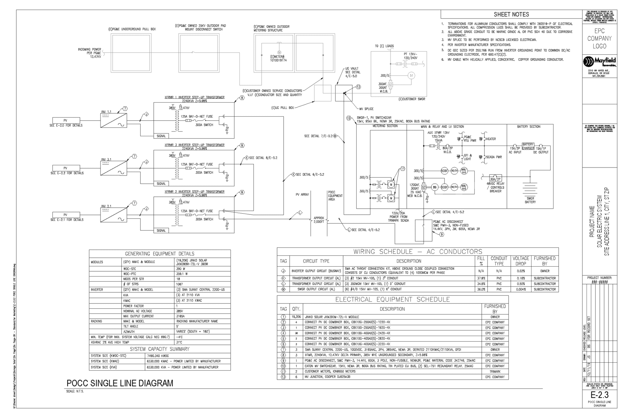
Single- or Three-Line Diagram
Here we are looking at the meat and potatoes of the permit package set. Although every sheet is just as important as the next, this sheet tends to present designers with the most difficulties as it pertains to the actual interconnection of the PV system to the existing onsite equipment. Depending on the size of a system, its single-line diagram (SLD) may extend for multiple pages. You may find yourself looking at something as small as a 100A subpanel on a residential service doing a load-side connection, or a 4000A switchboard located in a designated utility room with a line-side connection. Either way, this is where you will want to show how the PV system will be interconnected to the existing main service panel.
Generally, the pages in this section consist of sheet notes, which detail the equipment being installed and/or existing equipment, as well as wiring schedules where the designer or engineer will determine lengths and sizes of the wiring needed for both the DC and AC equipment.
The electrical equipment schedule, which is also included in this section of the plan set, specifies the quantities and electrical limitations of the equipment being installed. Some jurisdictions require voltage drop calculations, which you may opt to include here but can also be deferred to other pages in the plan set if you are limited by page dimensions. Note: Page sizes vary, so check with your permit office to see what they require for submissions. Typically, residential plan set requirements range from 8.5” x 11” to 11” x 17” while commercial- and utility-scale plan sets are generally sized to 24” x 36”.
Labels and Markings
On this page, you will see the applicable electrical labels as required by the National Electrical Code (NEC). States adopt NEC cycles independently--for example, Texas projects will adhere to NEC 2020 rules while Pennsylvania projects will adhere to NEC 2014--so be sure to check which cycle applies to your project early in the design process. As of today, most states are following the NEC 2017 guidelines but as we get further into 2021 more states will adopt the NEC 2020. Each Code cycle has updated Code sections and restrictions, so your labels should reflect any changes that have occurred during these code years.
Labels will vary depending on the type of system that is being installed. Typically, labels for residential or commercial grid-tied systems will call out the PV power source, DC and AC disconnects, AC combiner, system rapid shutdown and a map directory. Again, once you look up the applicable Code cycle for your project you can then determine what your labels need to specify. Since Code wording and sections change every three years, each label may look and read a little differently than a previous Code cycle. For off-grid or solar-plus-storage systems, you may need additional battery specification labels as laid out in NEC Articles 480 (batteries) and or 706 (energy storage systems). In general, the labels and markings page should be carefully reviewed for Code compliance based on the given system type and configuration.
Specifications
Last, but certainly not least, we have the specifications sheets. At the end of the permit drawing package, you will typically see multiple sheets in sequence, with each sheet overviewing the equipment being used for the project. These will include the module(s), rapid shutdown, module-level power electronics (MLPE), inverter(s), mounting rails, attachments, batteries (if used) and any other photovoltaic equipment associated with the project.
As always, check with your local AHJ about their specification sheet requirements. In some cases, sheets may not need to be built into the plan set; they may instead be printed out separately and included with the other permit submission materials. Find out what your AHJ requires and manage your plan set to their liking.
In this article, I have gone through the basic concepts of a typical solar permit package that would be provided for a standard set. Although each permit package will be different depending on the system size and type, the following information can be used as a basic tool to understand what is needed in any plan set for any PV project. If you have any questions about the PV design process or would like custom plan sets for upcoming PV projects, please contact our design team at design@mayfield.energy.


