

Technical Article
An Introduction to Power Quality in Solar Systems
Power quality is quite a buzzword in the electrical industry these days, no pun intended. How can we clearly define such a blanket term? Is it ever a significant worry in solar systems? There isn’t a concrete definition of power quality in the solar industry. Additionally, it can be extremely difficult and infeasible to catch or anticipate power quality issues in the design stage of a solar project. However, there is an easier way to heuristically look at power quality to help determine the source and solution of power quality problems.
Let me clarify here that I am speaking about power quality in commercial three-phase systems (although some concepts and issues may also apply to residential systems). The industry often considers power quality problems to be any events, transient or continuous, that prevent a system from operating at its perceived efficiency or from operating at all. However, it is helpful to at least categorize these power quality concepts into three separate buckets: Voltage regulation and power factor, resonant frequencies and transients, and harmonics.
Before considering how solar or battery storage may affect power quality, it is important to analyze these categories individually based upon the facility. Power quality is dynamic and there is no silver bullet to broadly improve power quality. For example, adding a reactor on the line side of a VFD will help smooth the harmonic profile, but will lower voltage and power factor. Adding solar to your facility will help with voltage regulation, but will increase the total harmonic distortion. Therefore, it is good practice to look at the facility as a whole to determine the biggest concerns. Does the facility have a long cable run and lots of inductive elements? Is it a wastewater treatment plant with lots of VFDs? Inverter based resources can either benefit or hurt power quality, depending on the facility and equipment it is integrating with.

Voltage Regulation and Power Factor
Voltage regulation and power factor are the most easily understandable and easiest to fix of the three. Voltage can drop due to large loads, long distribution lines, or several other factors. Poor voltage regulation can cause equipment to fail or run poorly. This can be mitigated by utilizing transformers to step up the voltage. Power factor is determined by how in phase the current is with the voltage; unity (current is completely in phase with the voltage) is the goal. Capacitive and inductive elements, such as transformers, induction motors, and capacitors, can induce a phase shift. This makes the current lead (inductive) or lag (capacitive) with respect to the system voltage. A low power factor means lower system efficiency and increased heating. Power factor correction capacitors can help by introducing capacitance into an inductive system to correct for current lag. Most new inverters can regulate voltage and correct power factor by injecting or absorbing reactive power and controlling the phase angle of the current. Therefore, these issues typically aren’t present in modern solar applications with inverters capable of Volt-Var and PF control.
Resonant Frequency and Transients
Resonant frequency and transients are abstract, unexpected, and difficult to capture or address in the design stage. A resonant frequency happens when system inductance-capacitance (LC) aligns with a dominant harmonic (more on harmonics later) order within the system. The LC of the system can amplify that harmonic and you can think of it like a positive feedback loop. This is usually a concern at facilities that have lots of capacitive or inductive elements such as capacitor banks, filters, or reactors. It can be fixed by adding reactance to shift the resonant frequency away from the dominant harmonics, utilizing detuned capacitor banks, or upgrading to a 12- or 18-pulse system (although this is expensive).
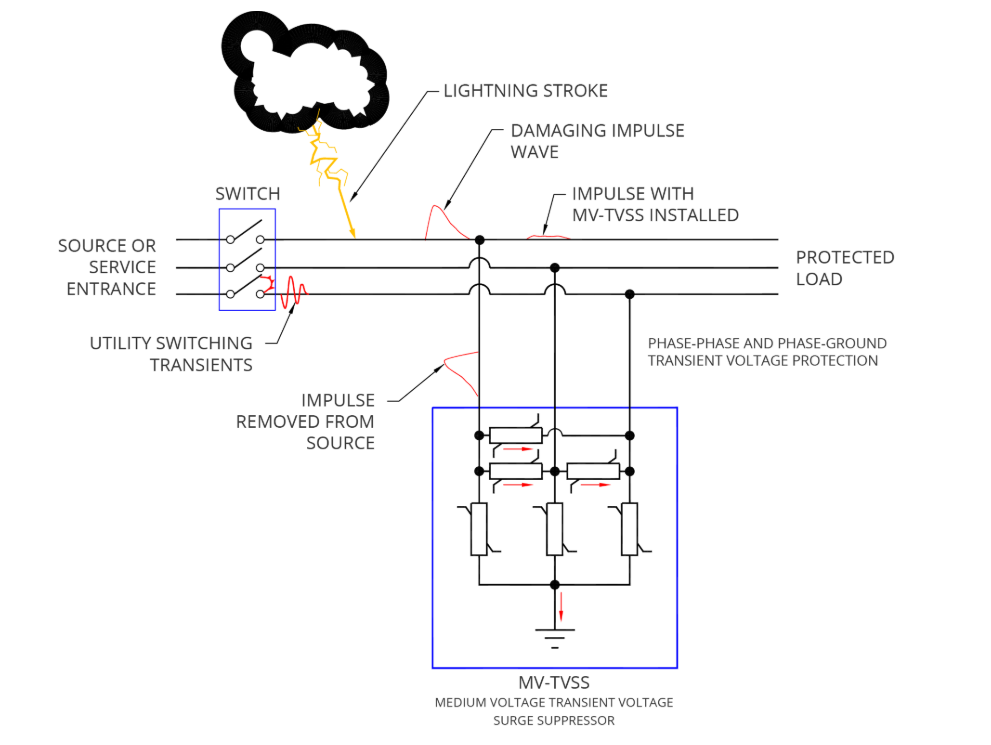
Transients are quick surges of voltage or current that can damage sensitive equipment. These transients can be caused by reclosers, vacuum breakers, load switching, or even lightning strikes. These can be addressed by adding RC snubbers, surge protection devices, or transient voltage surge suppressors to protect sensitive equipment.
Harmonics (an Introduction)
Harmonic issues are, for many, the most abstract and the most difficult to address when it comes to power quality issues. Harmonics in power systems are sinusoidal voltages or currents with frequencies that are integer (whole) multiples of the fundamental power system frequency (60hz in U.S. grid-tied systems). In behind-the-meter Solar PV (Photovoltaic) installations, power electronics such as inverters and converters are significant sources of harmonics. Proper attenuation of these harmonics is crucial to ensure minimal heat stress, to ensure high system efficiency, and to avoid system shutdowns and premature failure of components. Harmonics are a grid-wide challenge due to the possibility of harmonic transfer to and from the grid through the interwinding capacitance of isolation transformers. Understanding how these harmonics propagate through electrical systems and their interaction with the grid is critical for maintaining power quality.
The standard measurement for harmonics is THD (Total Harmonic Distortion). THD is the ratio of the sum of all the harmonic components (kW) compared to the fundamental frequency (kW). Taking 60hz as the ‘pure musical note’ signal, harmonics are the unwanted overtones. THD then tells us how ‘out-of-tune’ the system is. IEEE-519 specifies that the system THD should not exceed 5%, measured at the point of interconnection.
Common harmonics and how they are created
The most prevalent harmonics in a three-phase (60 Hz) system are typically the 3rd harmonic (180hz), the 5th harmonic (300hz) and the 7th harmonic (420hz).
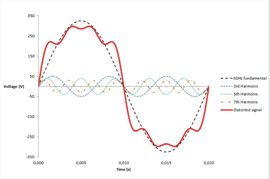
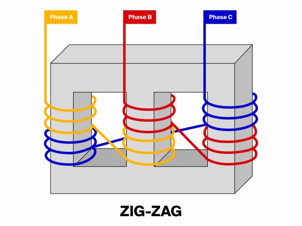
The third harmonic (along with all other “triplen” harmonics, such as the 6th and 9th) is a zero sequence and seen on the neutral. These harmonics are caused by unbalanced single phase loading on a three-phase system, LED lighting, switch-mode power supplies, and computers and servers. Triplen harmonics can be eliminated using harmonic mitigating transformers with zig-zag winding topologies, which utilize magnetic flux cancellation to attenuate these harmonics. Also, transformers with delta winding mitigate triplens (3rd, 9th, 15th) from propagating on the other winding as line currents. This is because the delta winding has no zero-sequence path to the other winding and will circulate (“trap”) these zero sequence currents within the delta windings. If there is a voltage imbalance between the three phases, it can distort the harmonic waveform, causing small non‑triplen harmonic components to appear on the other winding. Also, an extremely negligible amount of these 3rd order harmonics may pass from the delta windings due to capacitive coupling.
The 5th and 7th harmonics are negative and positive sequence harmonics (respectively). These are emitted from rectifiers or the front end of VFDs due to the 6 diodes used to rectify VAC to VDC. The diodes only allow current to flow in 60-degree intervals, creating a six-step waveform which mathematically produces harmonic orders of 6 +/- 1. These harmonics are seen on the phases, not the neutral.
These can be mitigated using a passive harmonic filter. A passive filter can be paired with each VFD to ensure that the 5th and 7th harmonics do not pass to the line side. Pairing one filter with multiple VFDs is not advisable because if any VFD is not running at a high load, the large filter's capacitance can cause a leading power factor. This leading power factor can cause issues within the system, especially if the system is intended to run on generator power.
Alternatively, an active harmonic filter can be tied in parallel with the system. This active filter can insert compensating corrective current and basically act as an opposing force to harmonics. Lastly, using two zig-zag transformers in parallel with a 30-degree difference in the fundamental phase shift between the two (e.g. 0o and -30o) will cause negative and positive sequence harmonics (typically the 5th and 7th) to be 180o out of phase and cancel these harmonics from traveling upstream.
Harmonics from the grid can also flow into a system, especially when grid impedance is high or when loads are unbalanced. These harmonics are often the result of facilities with high THD near the solar PV system, such as wastewater treatment plants with unmitigated harmonics from 6-pulse VFDs. A portion of these harmonics can be distributed to the grid and nearby sites, even though galvanically isolated by transformers, due to capacitive coupling between transformer windings. These harmonics can distort inverter output, which can affect power quality from the PV system. It can also increase thermal stress on inverter components due to harmonic currents.
Harmonic contribution from inverters
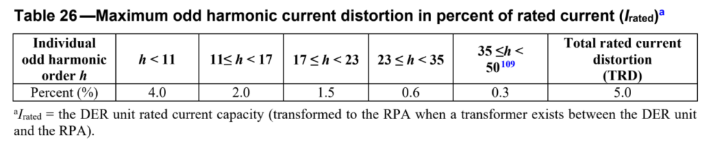
The biggest harmonic concern for the solar industry is often due to the inverters. Inverters use pulse-width modulation to convert a DC voltage into a pulse-width-modulated AC voltage. This pulse wave output is not always fully smoothed by an LC filter, and impure sine waves can propagate harmonics and reflective wave phenomena, especially through long cable runs. Odd harmonics (such as the 3rd, 5th, and 7th) are the most often seen because of the switching characteristics of the inverters. However, under UL 1741SB, certified inverters must demonstrate that their harmonic distortion levels do not exceed the maximum levels defined in IEEE 1547-2018. This requirement states that inverters must output less than 5% THD, and most inverters fall comfortably around 3% or less. Please note that this tests the output of the isolated inverter itself and is not tested, nor considered, with other variables within the larger electrical system design that might allow the inverter to contribute additional harmonics. The most important of these variables include grid impedances, possible site-specific resonance, and interaction among multiple inverters.
All of this is to say that most of the time, the concern of harmonics being produced by solar systems themselves should be low. However, microgrids with 6-pulse VFDs or other harmonic components, as well as facilities subjected to high harmonic contribution from the grid, may need harmonic mitigation strategies.
Power quality in solar and commercial three‑phase systems is often discussed as if it were a single, mysterious phenomenon, yet it is far more practical and structured when broken into its core components. It is difficult to anticipate and address power quality issues in the design stage. However, by understanding how each category of power quality behaves, engineers can diagnose issues more effectively and apply targeted, proven solutions.
Mayfield Renewables is an engineering consultancy specializing in commercial and industrial PV and microgrid engineering, including owner’s engineering services. If you’re unsure whether your project needs additional analysis or how power quality may affect system performance, a qualified EOR such as Mayfield Renewables can help you evaluate the risks & make informed design decisions.
-