Technical Article
2023 Update: How to Calculate PV String Size
When designing a solar PV system, knowing the minimum and maximum numbers of PV modules to connect in series as a string is critical. System designers regularly performed this calculation before the advent of dc optimizers. Optimizers — module-level power electronics (MLPEs) that dynamically manipulate the output voltage of modules — made this calculation much less common, especially in roof-mounted arrays that require rapid shutdown.
However, recent design trends have shifted to include systems using MLPE that do not actively manipulate voltages (e.g., straight rapid-shutdown devices), as well as the introduction of UL 3741 listed arrays that can, in some cases, eliminate the need for MLPE. Therefore, it is still critical to understand proper string-length calculations in the beginning stages of system designs. This post will describe the process in detail, using a hypothetical system with real components being installed today.
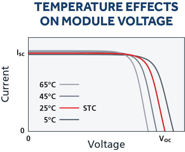
Note: The voltage of PV modules has an inverse relationship with temperature. A module’s voltage will increase in cold temperatures and decrease as it gets hotter. This relationship must be considered and calculated for proper string sizing.
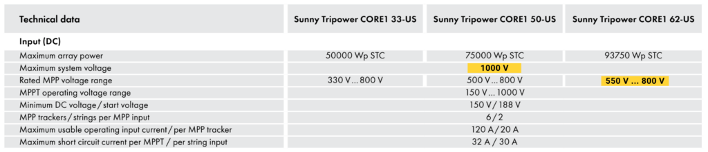
The primary goal of string sizing calculations is determining the minimum and maximum number of modules per string the inverter can handle. Too many modules on a string will exceed the maximum input voltage and damage the inverter or, worse, start a fire. If too few modules are on a string, the inverter might reduce its power output or turn off when the outside temperature is high. Let’s illustrate by looking at an SMA Sunny Tripower datasheet.
The inverter’s “maximum system voltage” sets the voltage limit for the maximum string length, typically either 1000 Vdc or 1500 Vdc for nonresidential inverters. The minimum voltage has multiple values listed on datasheets. But truly optimizing the string’s output means choosing a string length that lands within a more narrow optimal voltage range: the “rated MPP (maximum power point) voltage range.” Input voltages within this range allow the inverter to output at its rated value. In the example below, the SMA CORE1 62-US will produce its rated power output (62 kW) when input voltages are between 550 and 800 Vdc.
String Sizing Calculations
How to calculate minimum string size:
The minimum string size is the minimum number of PV modules connected in series required to keep the inverter running during hot summer months. The National Electrical Code (NEC) doesn’t address the effects of high temperatures on module voltages because that is considered a performance issue, not a safety issue. To calculate the minimum string size, we must first calculate the minimum output voltage, Module Vmp_min, each module will produce for the specific installation site. Then, divide the inverter minimum voltage by the calculated Module Vmin to get the minimum number of modules.
The following equation will calculate Module Vmin :
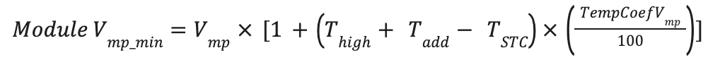
where,
Module Vmp_min = minimum module voltage expected at site high temperature [V]
Vmp = rated module max power voltage [V]. Found on the module datasheet.
TempCoef_Vmp = module max power voltage coefficient [%/°C]. Found on the module datasheet, it is always expressed as a negative value. Manufacturers typically display this value as the temperature coefficient for power. The change in voltage is responsible for the change in power; therefore, this coefficient should be used in the voltage equation.
Thigh = the ambient high temperature for the installation site [°C].
Tadd = temperature adjustment for installation method [°C].
The temperature is adjusted to take into account the installation method. Generally, roof-mounted systems get hotter than ground-mounted systems because there is typically less airflow, and the roof surface radiates heat.
- Roof mounted, parallel to the roof (<6 in. standoff): +35°C
- Roof mounted, rack-type mount (>6 in. standoff): +30°C
- Ground or pole mounted: +25°C
TSTC = temperature at standard test conditions, 25°C
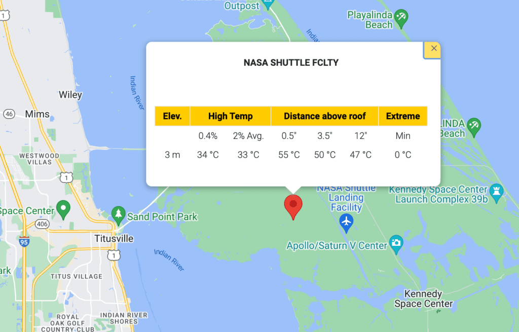
Designers can find site temperature data on Solar ABCs. There are three different options for Thigh, all are acceptable for design best practices:
- 2% ASHRAE high temperature (most commonly used)
- 0.4% ASHRAE high temperature (required for some incentives, slightly more conservative)
- Highest temperature ever recorded (most conservative)
Once we have a value for Module Vmp_min, we can calculate one endpoint of the string size range:

where,
Module Vmp_min = from the previous calculation above.Vmin_inverter = the inverter’s minimum rated MPPT (maximum power point tracking) voltage. Using the inverter's minimum operating voltage will ensure that the inverter will keep running. However, the MPPT function of the inverter may stop working. We recommend using the inverter's rated minimum MPPT voltage to ensure that the inverter can deliver the rated MPPT power.
Example:
Assume we’re designing a PV system on a flat roof in Portland, Oregon, using QCell’s PEAK DUO XL-G10 485 W modules and an SMA Sunny Tripower CORE1 62-US string inverter. Our relevant specifications are:
From the module datasheet:
Vmp = 45.63 V
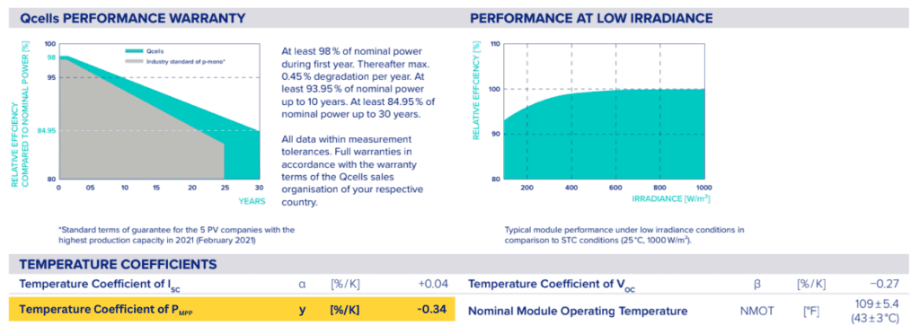
TempCoef_Vmp = -0.34 %/ °C
From the inverter datasheet:
Vmin_inverter = 550 V

From SolarABCs website and based on the site location:
Thigh (2% ASHRAE) = 32°C
Based on the parallel roof mounting, Tadd = 35°C
Again, TSTC = 25°C
First, calculate the Module’s Vmp_min
Module Vmp_min = Vmp x [1+ ((Thigh + Tadd –TSTC) x (TempCoef Vmp /100))]
= 45.63V x [1 +((32°C + 35°C - 25°C) x (-0.34 %/°C/100))]
= 45.63V x [1 +(42°C x -0.0034/°C)]
= 45.63V x [0.8572]
So, Module Vmp_min = 39.11 V
This calculation shows that the minimum module voltage expected at this site’s high temperature is about 85.7% of the rated module Vmp.
Then, calculate minimum string size:
String Sizemin = 550 V / 39.11 V
So, String Sizemin = 14.06
The minimum number of modules must exceed the calculated value, so round up to the next whole number. Here, our value is so close to 14 that a designer could probably justify landing on 14, but rounding up is the answer if we don't allow for additional context.
The minimum string size, then, is 15 modules.
How to Calculate Maximum String Size:
The maximum string size is the maximum number of PV modules that can be connected in series and maintain a voltage below the maximum allowed input voltage of the inverter. The Module Voc_max is calculated using the coldest temperature when the modules produce the highest expected voltage. This voltage is considered a safety concern and is addressed by the NEC.
Unlike our adjustments to the calculation for string performance in hot conditions, there is no adjustment or adder for mounting type for this calculation in coldest conditions.
The NEC does offer guidance and Table 690.7(A) for cold temperature adjustment factors when making this maximum string size calculation. However, the temperature coefficients listed on the manufacturer’s data sheets are preferred. The adjusted Voc calculation is expressed as:
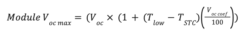
where,
Module Voc_max = maximum module voltage expected at site low temperature [V]
Voc = module open circuit voltage [V]. Found on module datasheet.
Voc_Coef = module open circuit voltage coefficient [%/°C]. Found on the module datasheet, it is always expressed as a negative value.
Tlow = lowest expected ambient temperature for the site [°C]. The best practice is to use the data provided by ASHRAE for the mean extreme minimum dry bulb temperature. For some designers, the second best practice in this scenario is to use the lowest recorded temperature. Either temperature value can be justified and will result in proper system design.
TSTC = temperature at standard test conditions, 25°C.
Now, with a value for Module Voc_max, we can calculate the top endpoint of the string size range:

where,
Module Voc_max = from the previous calculation above.
Vmax_inverter = the inverter's maximum allowable voltage [V]. Found on the inverter datasheet.
Example:
Assume, again, that we’re designing a PV system on a flat roof in Portland, Oregon, using QCell’s PEAK DUO XL-G10 485W modules and SMA Sunny Tripower CORE1 62-US string inverter 93.75 kW, 1kV, then our relevant specifications are:
From the module datasheet:
Voc = 53.63 V
Voc_Coef = -0.27 %/°C (remember: per K and per ℃ are analogous)
TSTC = 25°C
From the inverter datasheet:
Vmax_inverter = 1000 V
From SolarABCs website and based on the site location:
Tmin = -6°C
First, we will calculate the Module Voc_max:
Module Voc_max = Voc x [1 + (Tlow –TSTC) x (Voc_Coef/100)]
= 53.63 V x [1 + (-6°C – 25°C) x (-0.27 %/°C /100)]
= 53.63 V x [1 + (-31°C) x (-0.0027/°C)]
= 53.63 V x [1 + (0.0837)]
= 53.63 V x [1.0837]
Module Voc_max = 58.12 V
This calculation shows the maximum module voltage expected at this site's low temperature is about 8% higher than the rated module Voc.
Next, we will calculate the maximum string size:
Max String Size = Inverter Vmax / Module Voc_max
= 1000 V / 58.12 V
Max String Size = 17.21
Note: Here, we will round down to the nearest whole number.
Maximum string size is 17, and our range is 15 to 17 modules.
Conclusion:
To recap, we calculated the range for the number of modules in a string. We found that the total string voltage on the hottest day shouldn’t drop below 550 V or exceed 1000 V on the coldest day. Even if the operating voltage range of 450 V appears large, the calculated string size range, based on all the factors captured in the calculations, was really quite small: between 15 and 17 modules per string.
In general, best practice is to choose the largest possible string size while understanding that additional factors are not captured in the above equations. Following along with our example, that would mean setting a string length of 17 Qcells modules, as opposed to 15 or 16.
That said, it’s reasonable to make adjustments. When all factors are known and analyzed, such as changes in racking arrangement, tracking equipment choices, or updated site details, a string size of 15 or 16 modules may make more sense.
No two systems are the same, but we hope this article helps you find the optimal string size for your next PV project. If you’re looking for more PV or energy storage design and engineering support, we’re here to help. Contact us to get started.


