Technical Article
Understanding UL3741 and New Rapid Shutdown Solutions
Rapid shutdown requirements for PV systems have spurred innovations within the industry since the requirement first appeared in the 2014 National Electrical Code (NEC). The requirements imposed by rapid shutdown often seemed ahead of their time. So much so that the 2017 Code provided an allowance to waive a specific subsection for two years to allow the industry to catch up and create products to meet the Code. One of these delayed provisions in 2017 allowed systems “listed or field labeled as a rapid shutdown PV array” to provide the necessary limits of PV conductors within the array boundary. The Code-making panel (CMP) recognized such a listing would eventually exist and proactively provided the industry with a way to meet this requirement.
Then in 2020, NEC used an informational note bringing attention to UL standard 3741, Photovoltaic Hazard Control, specifically to address a method to meet this requirement. As with most standards, UL3741 took several years and revisions before release. The current version of the standard is dated December 8, 2020. It wasn’t until late 2021 that the industry started to see commercially available equipment with the UL3741 listing.
UL3741 and the NEC
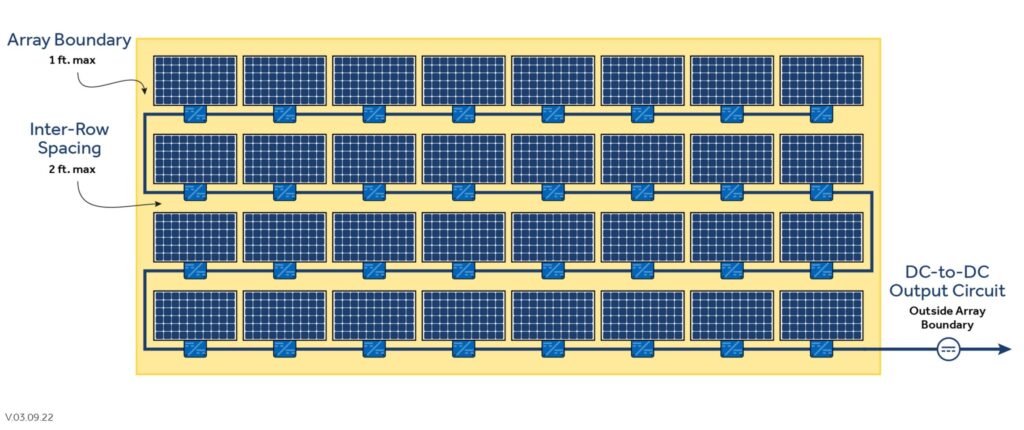
Before jumping into the application of UL3741 in PV installations, let’s take a step back and look at the Code requirements driving us to the standard. Section 690.12, Rapid Shutdown of PV Systems on Buildings, is familiar to most PV professionals. Regarding the UL3741 standard, our focus is subsection 690.12(B)(2), where the concern is controlling the conductors within the array boundary.
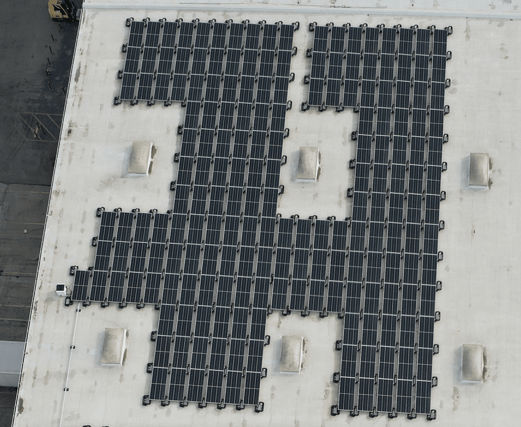
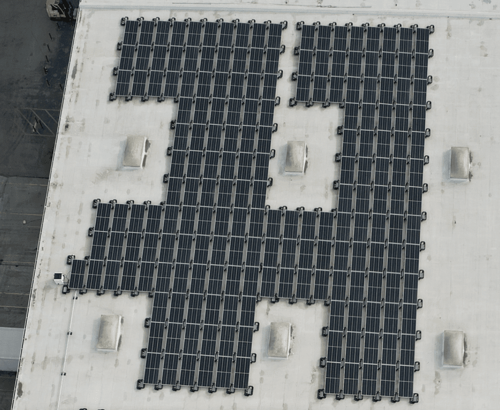
Installing module-level power electronics (MLPEs) on all rooftop arrays has been the most common solution to meet 690.12(B)(2). This installation method was the most straightforward way to limit the voltage of the conductors within the array boundary to less than 80 V within 30 seconds of initiation per 690.12(B)(2)(2). The 80 V threshold effectively eliminated the ability to place modules in series without an MLPE in the circuit before series connections. With the ability to list systems to the UL3741 standard, the options to meet 690.12 for rooftop PV arrays are increasing.
The 2023 NEC provides an excellent reference for the UL3741 requirements and installation applications. Many jurisdictions have not adopted the 2023 Code at this time, but I will use it for reference as it provides the best clarity on the subject. UL3741 is also allowed under the 2020 NEC. The 2023 version simply offers better language and clarity on the subject.
To begin, 690.4(B) introduces the term “PV hazard control system (PVHCS)” in 2023. It’s also worth noting that all definitions have been pulled from individual articles in 2023 and moved to Article 100. In this case, PVHCS does not appear in Article 100. Therefore the only references for this new term are in 690.4, 690.12, and 690.31.
690.12(B)(2) calls out the use of these PVHCSs to “provide shock hazard control for firefighters” as one method to meet the requirements to control the conductor limits within the array boundary. The addition of “provide shock hazard control for firefighters” is also added to 690.12(B)(2) to help clarify the purpose of these systems and who they serve. UL3741 provides an alternative to the previous sole solution of utilizing MLPEs on all rooftop PV arrays to meet the 690.12 requirements for conductors inside the array boundary.

UL3741 Overview
The premise of UL3741 was to define electrical hazards firefighters encounter when interacting with PV systems. The NEC threshold of reducing the conductors’ voltage within the array boundary to less than 80 V was never fully substantiated on actual risk to firefighters. UL formed a standards technical panel (STP) and engaged industry stakeholders, Sandia National Laboratories, and the US Department of Energy to gather data to define the hazards.
The result was empirical data measuring the potential shock hazards and risks firefighters face when interacting with PV arrays. The STP developed numerous parameters to substantiate the shock hazards imposed on firefighters. Items included the electrical resistance of standard, OSHA-required safety gear; the electrical body resistance of adult male and female firefighters; and the potential current pathways through a firefighter under various conditions.
This work culminated in defining shock hazards that accounted for voltage, current and resistance measurements. The result is a repeatable test method to ensure consistent and verifiable results. To pass the testing, manufacturers must prove that firefighters will not be exposed to shock hazards in various scenarios, including when firefighters fall on PV equipment with tools in their hands.
Applying 3741 and the NEC
The solar industry has not implemented this new standard broadly, at least not yet. Few products have completed the testing to date, but this solution will pick up. For example, MLPE manufacturers have listed their products to UL3741, allowing multiple modules in a series string. In addition, racking manufacturers have systems that enable string voltages up to 1,000 Vdc without using MLPEs. These are both deviations from what has become the norm of rooftop PV array installations.

The $64,000 question is, “how do I, as a designer and installer, apply this to my installations?” Code doesn’t give us a lot, other than a mention of following the manufacturer’s instructions in an informational note in 690.12(B)(2)(1). And expecting PV installers and code officials to read through UL standards is not realistic. But if you are interested, you can register for UL’s Digital View and read any UL standard you desire for free.
Ultimately, it comes down to reading the installation manual for the listed piece of equipment to understand the installation requirements. Manufacturers are required to list all the “critical components” for the installation to meet UL3741. Depending on the exact system, this may include specific accessories for the racking system, particular inverters, and even requirements for the wire clips. These details are essential, as the manufacturers used particular materials and configurations to meet the testing requirements.
Another resource for this information is the certification the testing laboratory provides to the manufacturer upon successfully completing the test. These certificates will include any specific components required to comply. Agencies such as UL and Intertek have informational directories for the equipment they test on their websites.
Understanding what defines the critical components and how they relate to the listing is probably the most confusing and challenging part of applying UL3741. The standard goes into great detail to define the various hazard levels and the probabilities associated with firefighter exposure to these hazards. This results in multiple pathways for manufacturers to meet the standard.
For example, suppose a manufacturer can test their system and prove the shock hazard experienced under a set of worst-case scenarios does not exceed Hazard Level 1 as defined in Table 8 of UL3741. In that case, the system requires no further testing or protection. Hazard Level 1 defines the maximum direct current exposure to firefighters without strong involuntary muscular reactions. This test method will allow many MLPE manufacturers to meet the standard without needing additional installation requirements, such as specific racking requirements or specific protections associated with wiring. Current MLPE options allow two crystalline modules wired in series and comply with this method.
The standard provides additional pathways for compliance when the system can experience a Hazard Level 2 or greater. The standard will require additional protections and installation methods, such as specific wire guarding, racking systems, and wire management. Multiple racking companies have used this method to pass UL3741 without using MLPEs.
For those interested, Appendix F in UL3741 provides examples of the calculations and methods used for the two scenarios mentioned. The appendix offers what constitutes the worst-case scenario and how the STP used a combination of current and multiple resistance levels to determine the maximum allowable voltages.
Conclusion
UL3741 systems go against the grain of “typical” installations, so installers can expect some pushback from jurisdictions. As with many other advances within our industry, this will require patience and education to code officials and the firefighting community. Overall, the transition to providing systems that offer shock hazard control for firefighters in a defined way is good for the industry.
Contact our team to inquire about Mayfield Renewables services—including system design, specialized consulting and educational programs. Contact us to start a project or learn more.


