Technical Article
Grounding Transformers for DER: What They Do and Why They’re Needed
One thing I’m particularly passionate about is working on and looking at old automotive technology. My latest passion project has been an old Mercedes, which, while beautiful, has a few frustrating components and systems that have been a pain. I’m often left scratching my head, wondering “what in the world was this for?” or “why did they choose to implement this?”
Grounding transformers give engineers that same feeling. They’re essential in certain systems, but their purpose, behavior, and requirements aren’t immediately obvious unless you’ve worked with them directly. A grounding transformer requirement can turn an easy project into a very frustrating one, as specification and implementation do not follow typical design logic for transformers.
Grounding Transformers: Purpose and Origins
Grounding transformers have a surprisingly long history, and their primary purpose was to add a ground source to a delta system when the industry moved toward system grounding as a standard practice. Industrial buildings have installed grounding transformers as far back as the 1920s. These were sometimes chosen to be the ground source instead of wye feeder source, or to ground a delta fed system. Since grounding transformer implementation enables control of the zero‑sequence impedance, and therefore the ground‑fault current level, these systems could be set higher or lower depending on protection and equipment requirements. This is just one of the functions grounding transformers have, but I’ll spare you the full history lesson. Let’s focus on when and why they might be required for inverter-based resources (IBRs).
Effective Grounding and TOV
IBRs and grounding transformers have a contentious relationship. Lots of questions have been raised regarding their need and functionality, which is why their requirements differ from utility to utility. The crux of this disagreement comes from what utilities deem “effective grounding” per IEEE-142.
IEEE-142 defines effectively grounded systems as:
“Grounded through a sufficiently low impedance such that for all system conditions the ratio of zero-sequence reactance to positive-sequence reactance (X0/X1) is positive and not greater than 3, and the ratio of zero-sequence resistance to positive-sequence reactance (R0/X1) is positive and not greater than 1.”
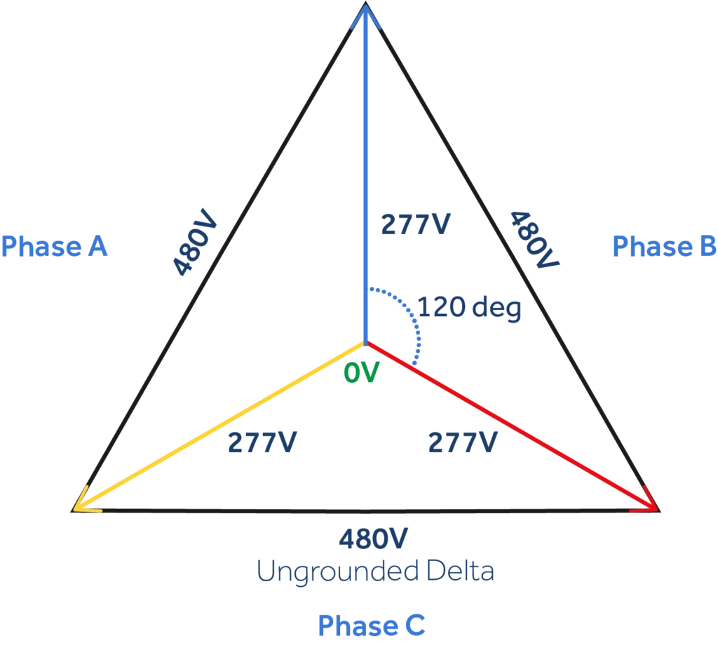
The main fear here is of something called “temporary overvoltage” or TOV. In a balanced three‑phase system, the neutral voltage remains near zero because the phase voltages sum to zero—irrespective of whether physically grounded or floating.
When a ground fault (or any other transient unbalance) occurs, the system becomes unbalanced and zero‑sequence voltage is introduced. This shifts the neutral point (neutral displacement), causing the un-faulted phase‑to‑neutral voltages to rise, potentially reaching overvoltage levels depending on the grounding method. This can cause damage, specifically to line-to-neutral connected and rated equipment, as the line-to-neutral voltage during this shift can exceed the typical line-to-line voltage. Phenomena such as ferroresonance or arcing ground faults can further exacerbate these voltage spikes. The takeaway? A neutral shift can cause an overvoltage event on an ungrounded or a system that does not meet the “effective grounding” requirements of IEEE-142.
The TOV Concern for Inverter-Based DERs
So, why is this a concern on inverter-based resources? Well, most inverters do not provide a solid neutral connection. Photovoltaic inverters are built to work as balanced, three-phase current sources, so a neutral conductor isn’t needed for power export. Inverter manufacturers discourage adding a solid neutral connection or adding a grounding resistor because it complicates meeting UL 1741 and IEEE 1547 standards. The main reason for not having a solid neutral connection is to prevent short-term imbalances in phase switching times from causing unwanted neutral currents.
Allowing the neutral to “float” avoids unwanted triplen harmonics from occurring and negatively affecting the inverter. Additionally, a solid neutral connection can interfere with the inverter’s ability to detect phase voltage issues and cause unwanted currents. This means that the power generation system may lack effective grounding to prevent and address faults and overvoltage.
Another complication is that grid‑following inverters contribute very little ground‑fault current. They behave as controlled current sources and cannot drive the zero‑sequence current needed to stabilize the neutral during a line‑to‑ground fault. A zig-zag or wye-delta grounding transformers may be required to effectively ground the system.
How a Grounding Transformer Can Meet Effective Grounding Requirements
Why is a grounding transformer needed if there is already a neutral reference in the system? Unfortunately, the answer isn’t very straightforward. It all depends on the transformer winding configuration leading up to the inverters, including the utility’s feeder transformer.
Even a wye-wye transformer may not provide effective grounding. Without going into great detail, if the neutral of a substation transformer is connected to the primary neutral of a wye-wye utility feeder transformer, when the feeder breaker opens during a fault, the PV system is now effectively isolated from the zero-sequence network of the circuit and subject to TOV.
Another reason could be that the distribution transformers implemented do not fit the effective grounding criteria; for example, by having a different X/R or zero-sequence reactance than what the utility deems needed to meet effective grounding. At the end of the day, all of this is dependent on utility configuration, as well as interpretation of IEEE 142 and IEEE 1547.
Effective grounding requirements are a topic of debate among utilities and engineers, and are often contested when applied to inverter-based resources. The original criteria of this requirement was centered around generation sources with mechanical inertia, such as synchronous generators. Grid-following inverters don’t naturally have sub-transient reactance or provide ground current, and the lack of mechanical inertia means the risk of an overvoltage event is short lived. This is especially true of grid-following inverters which cannot sustain a phase-to-ground overvoltage like a generator can. Still, some utilities enforce this effective grounding requirement for inverter-based resources, which is likely due to the lack of real-life data on whether these events are prevalent in such systems.
Design Philosophy and Differences
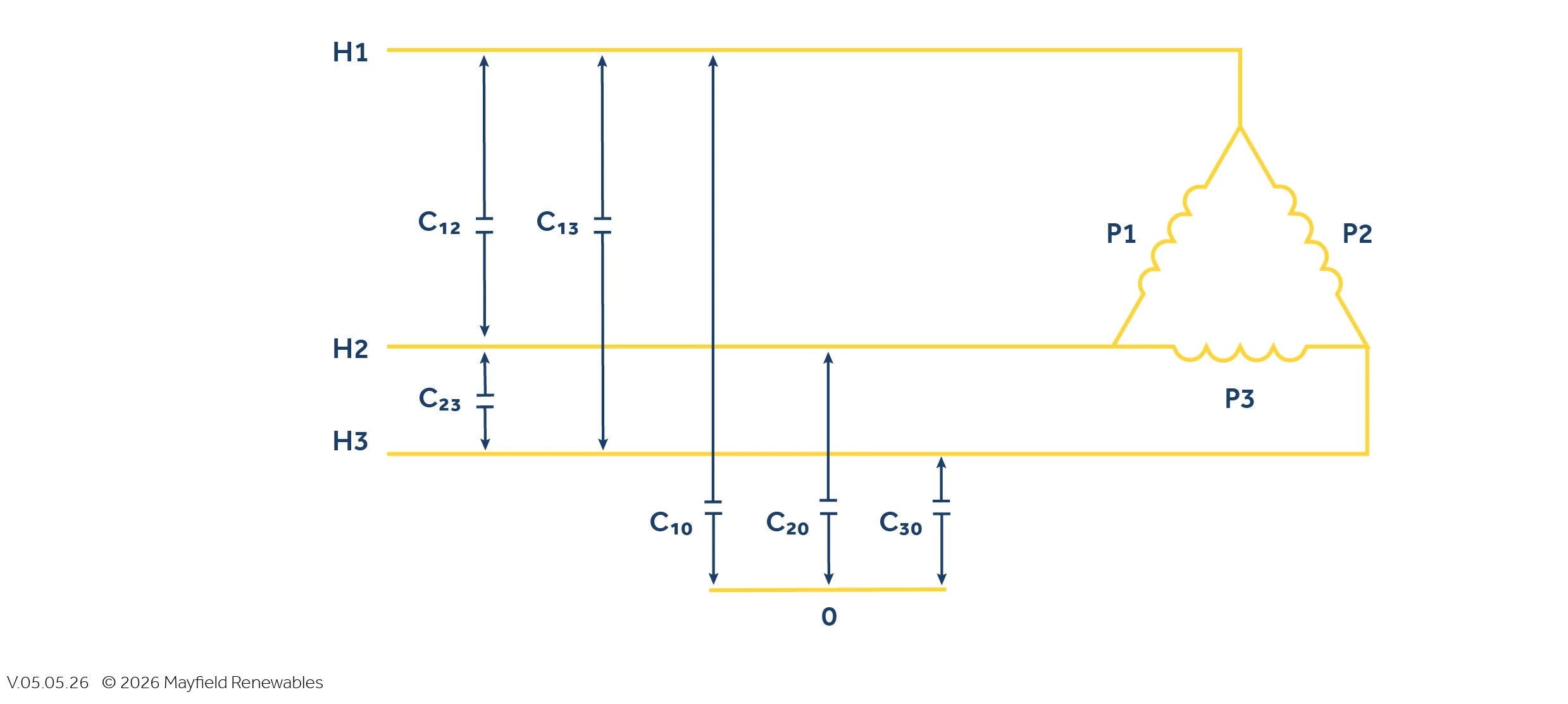
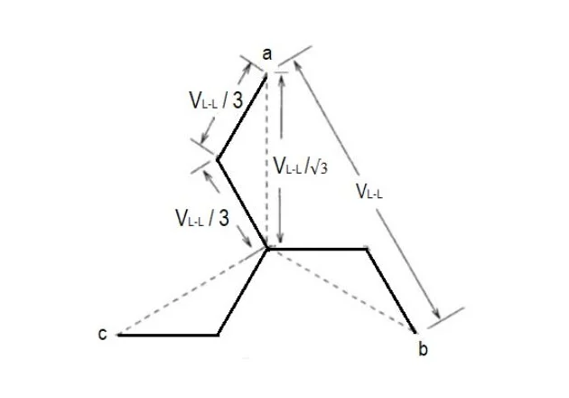
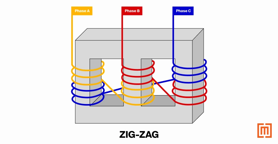
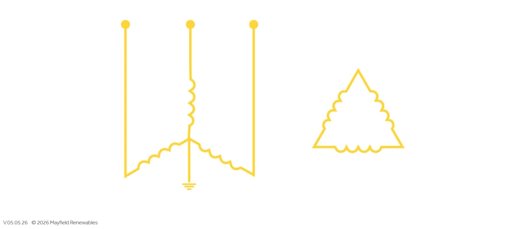
Now that we have covered grounding transformer function, we should establish their design philosophy. Grounding transformers have two typical winding configurations. The most widely used is a zig-zag configuration, in which each phase is arranged with two separate coils which are wound on different core legs. For example, half of phase A is wound on leg A, and half is wound on leg C. So, the phases are zigging onto one leg and zagging onto the other, hence the name.
The other design, which is less popular due to its larger footprint and higher cost, is a wye-delta transformer. This vector and winding configuration is identical to a normal wye-delta distribution transformer. However, it will have extremely different design specifications, which is due to both their implementation and the effective grounding requirements mentioned earlier.
Both transformers also will help eliminate triplen harmonics. For a zig-zag, this is due to the winding configuration which creates magnetic opposition between the windings to cancel out the triplen harmonics. The wye-delta also does this, but by trapping and circulating harmonics within its floating delta. This is more of a byproduct of the design and implementation of grounding transformers, but it does help them deal with the zero-sequence events they are tasked with facing.
One thing that has bothered me since I started working with grounding transformers is the term itself. While they are clearly wound like transformers, they don’t serve the same function as your typical transformer would. The most glaring difference is that grounding transformers are installed in parallel, not in series. This is because they are not meant to serve loads or change voltage like a typical transformer. Instead, they are meant to form an effective ground. Grounding transformers also have far different specifications than other types of transformers. For these reasons, I consider the term “grounding bank” to be more accurate for these devices, and a better way to think about these than if they were traditional transformers.
The Specification Problem
Specifications are important to talk about here, as someone unfamiliar with grounding transformers may struggle to get this right, or even quotable from the manufacturer. What should and should not be considered?
The first thing that should be considered is that either the zero-sequence impedance or reactance must be specified to establish your effective ground, and the requirement will depend on utility guidelines. This rating is quite important from a utility standpoint, as they need to consider that during a fault, it will be an additional zero sequence source that may pull enough current to affect the clearing time and effectiveness of their upstream protective equipment. The margin given by utilities for this rating is typically only around +/- 10%, which is a small margin that only allows for standard manufacturing tolerance.
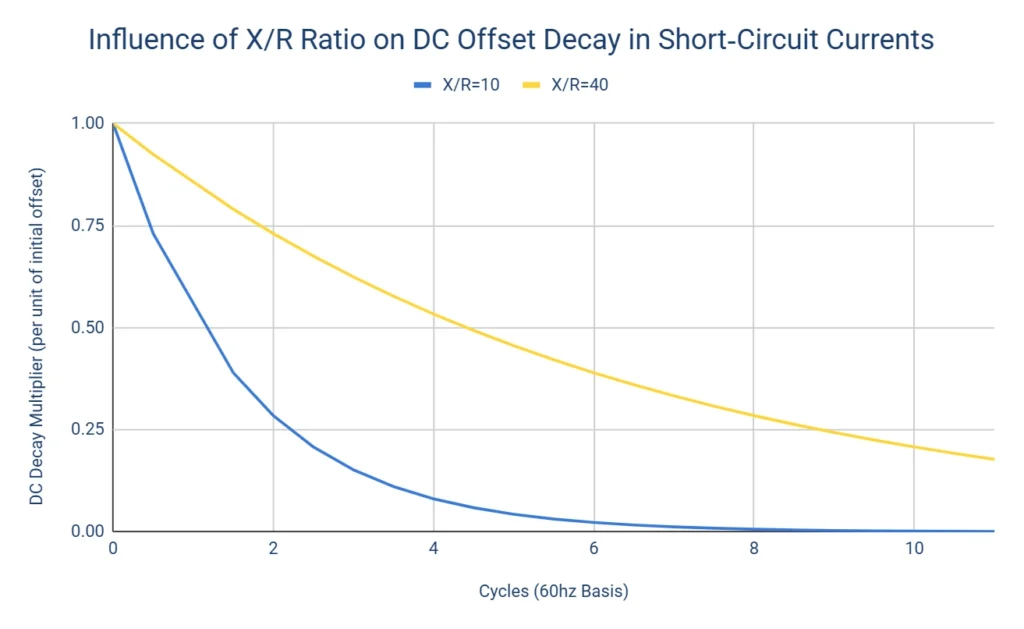
The X/R ratio of the grounding transformer must also be specified. This will also affect the TOV behavior, and the upstream protective equipment. For example, a higher X/R ratio can often mean a higher asymmetrical ground-fault current, which can increase TOV severity. It should also be mentioned that grounding transformers typically must be wound in copper, due to strict impedance and X/R requirements. These two specifications are the most critical requirements from the utility.
But that’s not all that needs to be considered. Two other important factors are the continuous neutral and short-circuit withstand capability. The continuous neutral of a grounding transformer ensures the transformer does not overheat during normal operation. Because the transformer is in parallel with the system and does not carry a load, it will only see current when the system is unbalanced. In virtually all cases, the rating should be at least 3% of the short-circuit current withstand rating (per IEEE 32), but it is often advisable to have an additional buffer for unforeseen system imbalances.
Another consideration is whether your grounding transformer will be implemented for a microgrid application. Under islanded conditions, this grounding transformer will have to support any line-to-neutral loads and may see additional imbalance. The simplest specification here will be the short-circuit current withstand rating. Since the grounding transformer will often be the only zero sequence current source during a fault, it can often be specified based purely on the zero-sequence reactance of the grounding transformer itself. The caveat here is that if you do have other zero-sequence sources still in circuit during a fault, these must also be considered as additional sources of current. Then, a withstand duration must also be specified. Withstand durations for inverter-based systems (5-10 seconds) are typically much shorter than for synchronous generator systems (up to a minute or longer).
If a wye-delta is specified, the secondary (delta) voltage must also be specified. Typically, it is left at 480 V. The voltage is a non-factor, as it is installed in parallel and will not have any attached loads. A neutral reactor or resistor might also be specified to form an impedance or resistance grounded system, but this is an atypical requirement for inverter-based resources.
Along with the grounding transformer, it is also prudent to mention that peripherals such as a breaker, current transformer and possibly even a relay will likely be required by the utility for this grounding transformer. Another consideration is that the implementation of this grounding transformer will change the line-to-ground and line-to-line-to-ground short-circuit characteristics of the system, so it is often worth getting a power study done to ensure that your specified protective equipment will still work as intended.
Grounding transformers can be a headache and mystery, but hopefully this article has shed some light on the what, when, and why of this component. System requirement review and studies can be performed by Mayfield to determine the suitability of the transformer within your system. Are you looking for an engineering partner who can navigate consulting on product selection and value engineering opportunities? Reach out to discuss how we can support your team today.
Mayfield Renewables provides design and engineering services for solar-plus-storage systems, and feasibility studies for microgrid systems. Contact us today for a consultation.


