Technical Article
Welcome (back) to Code Corner!
The team at Mayfield Renewables goes above and beyond to stay informed on the latest trends impacting the solar and energy storage industries, and we strive to translate these complex topics into digestible content for the broader community. With that in mind, we’d like to introduce our new video series, Code Corner.
Name sound familiar? Perhaps you remember the column of the same title in Home Power magazine. Ryan and I thoroughly enjoyed working with the Home Power staff and contributors on that column and are delighted to revive the concept in a more dynamic medium.
Over the months to come, Mayfield Renewables’ subject matter experts will share brief but informative conversations on specific building, electrical and fire code articles and how they impact PV and solar-plus-storage systems. First up: the scope of National Electrical Code (NEC) Article 690.1.
You can watch part one of our discussion linked below. We’ll also provide an overview here on the blog to help you follow along.
What is NEC 690.1?
Per NEC 2020, “This article applies to solar PV systems, other than those covered by Article 691, including the array circuit(s), inverter(s) and controller(s) for such systems. The systems covered by this article include those interactive with other electric power production sources or stand-alone, or both. These PV systems may have ac or dc output for utilization.”
This article is applicable to systems smaller than 5 MW. Larger systems are covered by Article 691.
What’s new and why does it matter?
NEC updated the diagrams relating to Article 690.1 in 2017. Although these might seem like small tweaks, they come with significant implications. What’s new here is the inclusion of the PV system disconnect, which gives us a clear definition of where the PV system ends. This is especially helpful when we think about issues like rapid shutdown and what components need to be controlled during that process.
Let’s take a look at some examples below, featuring custom illustrations by our Content Strategy & Production team.
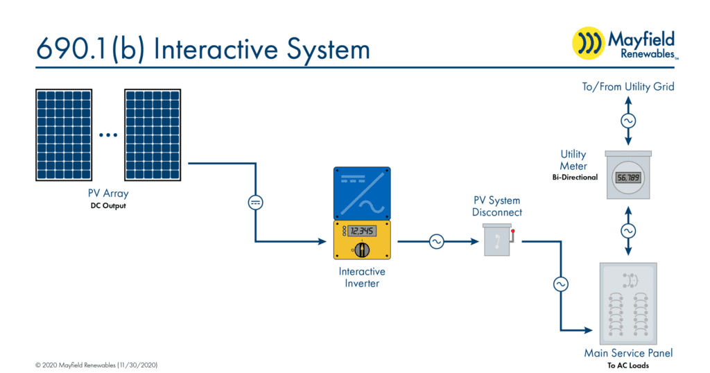
First we have a typical interactive PV system, where dc power leaving the solar modules travels through an interactive inverter, which converts the power to ac before connecting to the utility grid. Note that the PV system disconnect occurs between the inverter and the main service panel. This placement enables the rapid shutdown of all equipment required to convert solar energy to electricity without impacting operations of any equipment located downstream.
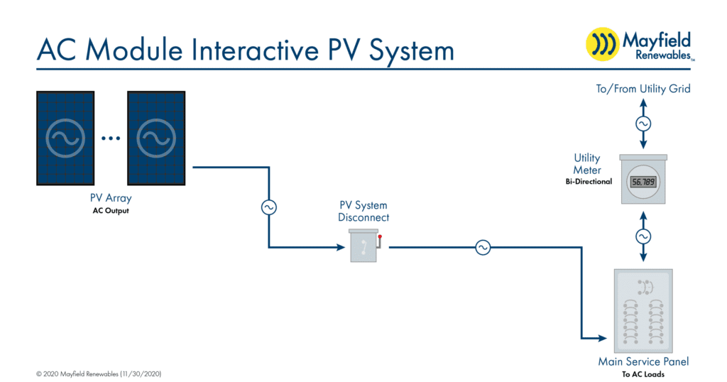
Next we have the increasingly popular ac module system, where dc-to-ac conversion happens at the module level rather than through a centralized inverter. Here, all equipment required to convert solar energy into electrical energy is housed within the array itself (i.e., no separate inverter is required), so our PV system disconnect just needs to be placed between our array strings and the main service panel.
This becomes a bit more complicated when we look at solar-plus-storage systems.
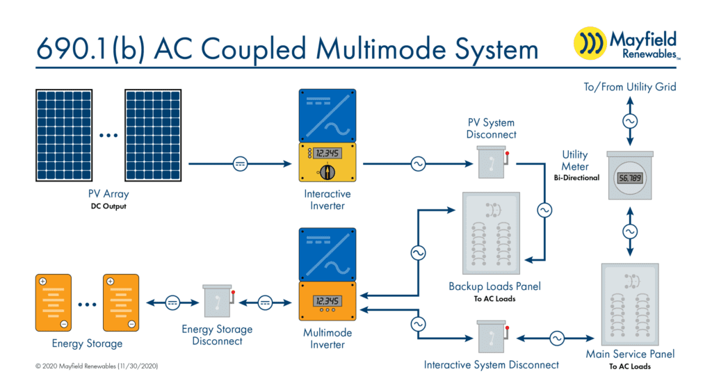
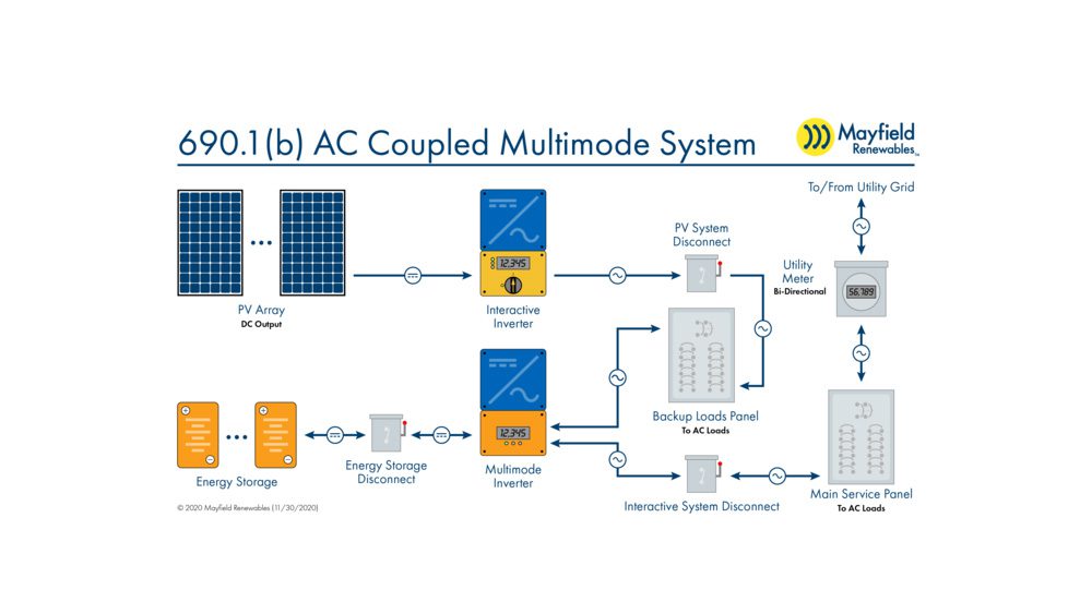
This is an ac-coupled multimode system, where the two power production sources are combined on the ac side of the bus. We see this most often where a PV system previously existed and the storage component was added later, or with a packaged energy storage system (e.g. the Tesla Powerwall) where there’s only an ac output. These systems employ two inverters: an interactive inverter as with the PV-only system above, and a multimode inverter.
Notice that while the disconnect output still clearly defines the end of the PV system—meaning only the highlighted portion of the diagram falls under the purview of NEC 690—it no longer taps into the main service panel. Instead, the PV system disconnect is routed to a backup loads panel. This configuration essentially creates a synthetic grid and keeps the PV interactive inverter (and thus PV array) online during grid outages.
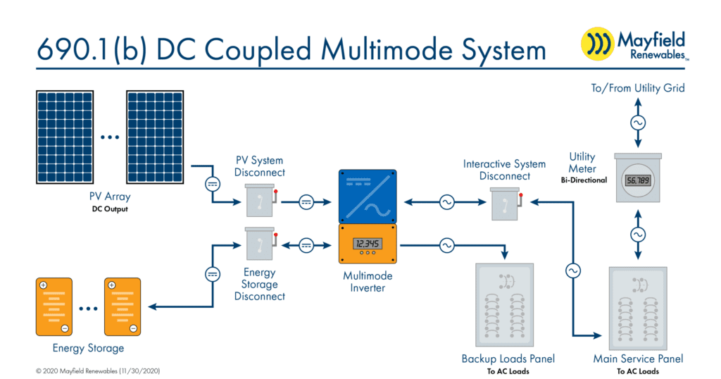
Finally, we have a dc-coupled multimode system, historically found when the PV and storage components were installed at the same time. Because the power production sources are combined on the dc side of the bus, we don’t need any extra energy conversion components. This means that, similar to our ac module system above, our PV system disconnect shall be located immediately downstream of the PV array.
As we noted at the top, the diagram revisions laid out in Article 690.1 might seem small, but the inclusion of a clear PV system disconnect point is critical in terms of NEC Article 690 applicability and beyond.
Stay tuned for our next installment of Code Corner, which tackles NEC 706.1. Updates will be posted to our YouTube and LinkedIn pages.


