Technical Article
Designing Microgrids Around the Limits of 240V Open Delta Systems
If you work in microgrids long enough, you’ll eventually run into a 240 V open delta service. Typically, this is at the worst possible time, when you’re three projects deep and on top of that your car won’t start. It’s a configuration that works fine for legacy distribution, but it becomes a real engineering puzzle when you try to pair it with modern BESS hardware. This, along with other issues, is why utilities rarely install new 240V open delta banks.
How is an Open Delta Formed?
An open delta is most typically formed by a bank of two single-phase transformers. This allows for a three-phase 240V distribution feeder that also has the capability of providing single phase 120V. Obviously, this is perfectly fine for residential applications in which 240V and 120V are so common.
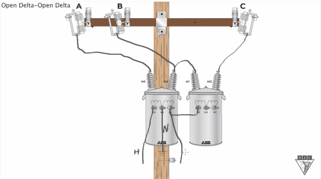
Source: Northwest Lineman College
Why Are 240V Open Delta Systems a Problem for Microgrids?
So why does it pose a problem for microgrid systems? The answer to this lies in the way transformer vectors are formed. A large majority of commercial BESSs are meant to output 480V. This necessitates an isolation transformer to mate the 240V open delta system and the 480V BESS output.
The sensible solution would be to get a 240V delta to 480V wye transformer, right? This would make the two systems compatible and be the correct configuration in most cases. However, the problem lies with the 120V loads during an islanding event. Open delta transformers have no problem providing these loads. However, closed delta systems, such as those found on a distribution transformer, cannot supply large 120V loads.
Why Can’t High‑Leg Delta Distribution Transformers Support Large 120V Loads?
Why is this? It has to do with the way that 120V tap is attained. High-leg delta distribution transformers will derive a midpoint in-between the A and C windings, which creates a 120V tap. This is often referred to as a delta high-leg, since between A and C phases, A-to-midpoint is 120V and C-to-midpoint is 120V, and b-to-midpoint is 208V.
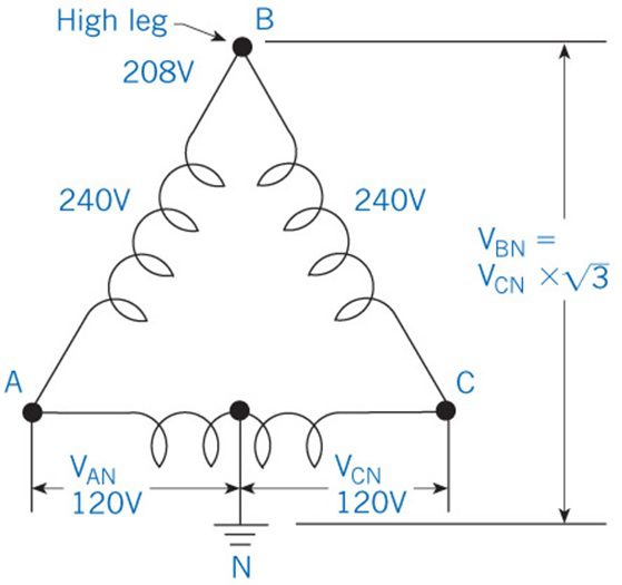
Source: MACROMATIC
This tap is pulled from the winding, and although it is useful for small 120V loads, it is not meant for large loads. Typically, it is rated at around five percent of the transformer’s KVA rating. Therefore, if you have a transformer that is rated for 75kva, the single phase midpoint tap will only be capable of supplying around 3.75kva of loads. This is a structural limit of the winding geometry. The issue comes with the fact that the 240V delta is a closed system. It circulates current and voltage within the delta. The difference between the 120V potential between the midpoint and the A and C windings, and the 208V potential between B winding and midpoint, means that you will have negative sequence no matter how the 120V tap loads are portioned between the A and C windings. This is just one of the reasons why the midpoint is not fully rated.
What Happens During Islanding?
Ultimately, this is not a problem when the open delta system (grid) is up and providing those 120V loads. However, once the system islands, you are now feeding from the BESS isolation transformer, which again, is not rated to provide large 120 V loads. These 120V loads will need to be fed using separate single phase 240V to 120/240V transformers, as these transformers will be capable of supplying the 120V loads that the BESS isolation transformer will not.
I'm sure you're probably wondering, "Sam, why can't I just use another open delta transformer to couple the BESS and the system?" There are a couple of reasons for this, but the main ones are you will have worse voltage regulation, lower load balance tolerance, and significant negative sequence currents and harmonic distortion. Battery storage systems work best when they are provided with balanced phase voltages, low negative sequence voltage, and stable phase angles. None of which are provided by an open delta transformer.
Another configuration that you may initially think of is a wye system. However, the neutral of a system will be the phase-to-phase voltage, divided by the square root of 3. This is why a wye could not be used, as the neutral voltage output of a 240-wye system would be 139V. This is much too high to be suitable for residential loads. If you’re wondering why you have never seen a 240 wye system, this is why.
The typical solution you'll want is dedicated single phase 120V transformers to be installed downstream and balanced to make sure you aren't unbalancing the system or pulling too much off a particular leg of the Delta system, however, this is mostly up to how the system is designed and the loads are partitioned.
Microgrid design is a complex subject with many nuances. Creating a functioning system requires all components to work harmoniously together, and it is easy to overlook these issues. The best way to avoid problems like these is to consult with subject matter experts and review the feasibility of your microgrid before implementation.
System modeling and load studies can be performed by Mayfield to determine the suitability of the system. Are you looking for an engineering partner who can navigate consulting on product selection and value engineering opportunities? Reach out to discuss how we can support your team today.


