Technical Article
Code Corner: NEC Article 705.12(B)(1)
It’s time for another installment of Code Corner, where Justine and I turn complex regulations related to PV and solar-plus-storage systems into bite-sized overviews. Here, we’ll focus on NEC 2020 Article 705.12(B)(1), which is all about utility interconnection on feeders. Take a look at the video below, or keep scrolling for our cheat sheet.
What is NEC 705.12(B)(1)?
According to the National Electrical Code, “Where the power source output connection is made to a feeder, the feeder shall have an ampacity greater than or equal to 125 percent of the power-source output circuit current. Where the power-source output connection is made to a feeder at a location other than the opposite end of the feeder from the primary source overcurrent device, that portion of the feeder on the load side of the power source output connection shall be protected by one of the following:
- The feeder ampacity shall be not less than the sum of the primary source overcurrent device and 125 percent of the power-source output circuit current.
- An overcurrent device at the load side of the power source connection point shall be rated not greater than the ampacity of the feeder.”
What does that mean and why does it matter?
Let’s break this down into simpler language and reference some helpful images created by our Content Strategy & Production team.
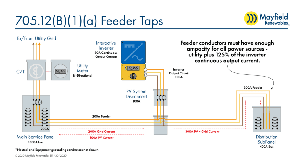
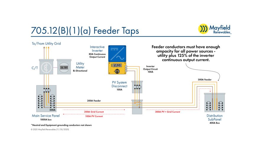
Here we have a system where we’re connecting the output of an interactive inverter to a feeder—a common setup in a commercial facility. Looking at the image, you will see that the main service panel has multiple breakers that connect to feeder conductors that lead to various subpanels throughout the facility.
In this scenario, the feeder conductors are the most logical utility interconnection point. According to Code, we need to size our inverter output conductors to at least 125 percent of the continuous output current. For an 80 A interactive inverter, that means we will need to size our conductors to handle at least 100 A (80 A x 1.25).
When an inverter is connected to the feeder, we need to look at what’s happening on either side of the connection point. Starting from our PV connection point and moving to the grid connection on the left: We can never have more than 200 A coming from the grid and no more than 100 A going back to the grid from the PV system, so the net maximum current this feeder will see is 200 A. There’s no cause for concern here.
Next, let’s look at the conductors downstream from the PV connection point. This is where things can get tricky. We can have 200 A coming in from the utility and another 100 A from the PV system, for a total of up to 300 A on that set of conductors. This means we either need a 300 A feeder or we need to ensure the conductor is properly protected by other means.
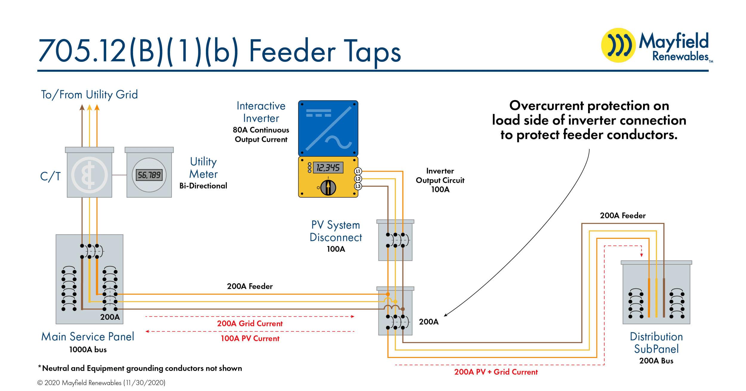
One way to protect the conductor is to install an overcurrent device, such as a circuit breaker, on the load side of the connection. This protects the downstream feeder from seeing more than 200 A and avoids the need to upsize the conductors.
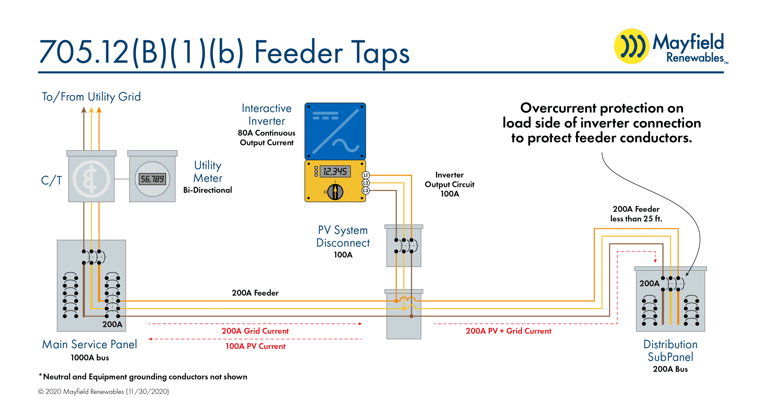
If this option isn’t feasible due to space constraints, we can also protect the feeder conductor by converting the distribution subpanel to include a main breaker. Here again, the conductor will never carry more than 200 A. (It’s important to note that in this case, the connection point must be located within 25 feet of the overcurrent protection, per NEC 240.21.)
Feeders are increasingly popular in commercial facilities, and we’re even seeing them in some residential applications. Regardless of project scope, understanding where and how to safely tie PV systems into an existing electrical infrastructure is essential. If you have questions on how to ensure your design complies with NEC 705.12(B)(1), our System Design & Engineering team is happy to help. Please reach out to us at design@mayfield.energy to start a project or learn more.


