Case Study
A Community-Driven Island Microgrid
Cascadia Renewables
Project Highlights
Location
Eastsound, WA
System Specs
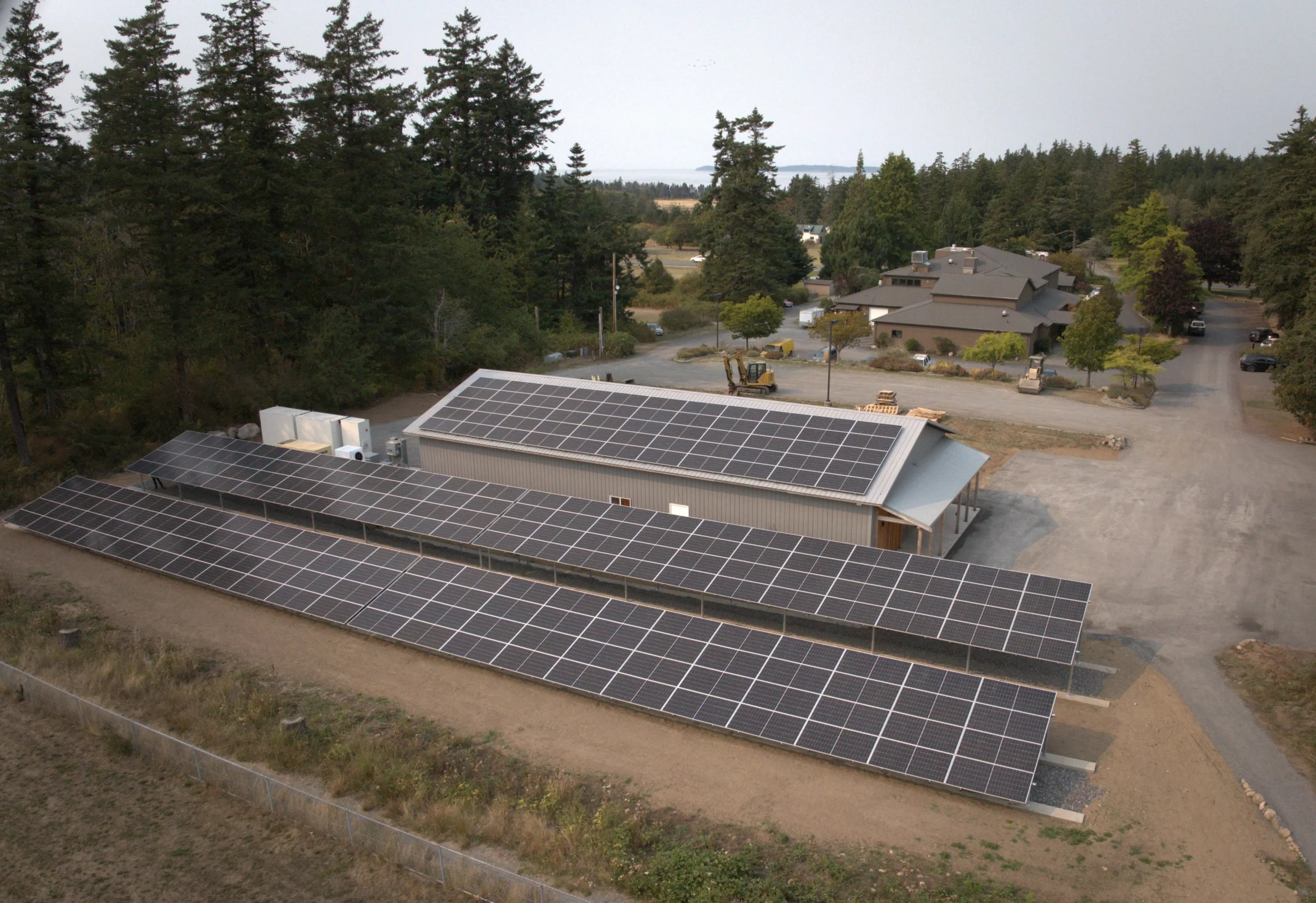
100 kW roof- and ground-mounted PV arrays
1,376 kWh energy storage system
Equipment
PV Modules: Heliene 144HC M10 NTP SL 580
PV String Inverters: SolarEdge SE100KUS
Battery: ELM MG2-ESS-688
Battery Inverter: EPC Power CAB1000

Challenge
One of the northernmost parts of the continental U.S., Orcas Island is roughly three hours (by car and ferry) from downtown Seattle and is connected to the mainland by a single undersea transmission line. Extreme weather events and grid outages can leave locals stranded for extended periods of time.
To protect their uniquely vulnerable infrastructure, the San Juan County Emergency Management (SJCEM) agency identified the Orcas Center as a facility that could function as a resiliency hub in an emergency. The location was conveniently central and well known community gathering place. The issue, however, was that the Orcas Center did not have the energy resources required to function as an island-able microgrid system.
With a site (Orcas Center) and primary goal (energy resilience) in mind, SJCEM set out to find the right mix of distributed energy resources to achieve key performance benchmarks while staying within space and budgetary constraints.
In other words, this island facility was interested in “islanding” from the grid.
Approach
Based in Bellingham, Washington and with a history of Pacific Northwest community-led microgrid development, Cascadia Renewables was selected as the EPC for the Orcas Center project. Cascadia worked with local partners from MZ Solar Consulting to perform preliminary analyses and Mayfield Renewables to lead planset development and to act as the electrical engineer of record.
By the time Mayfield became involved, Cascadia had already defined performance goals for the microgrid, and MZ had estimated the distributed energy resource (DER) sizes required to meet those goals. Mayfield validated the initial design for code compliance, worked with the Orcas Center and the local AHJ to determine equipment locations, and defined roles and responsibilities to fulfill the complex system controls functions.
Project Hurdles
There’s something to learn from every microgrid project, and the Orcas Center was no exception. We took away a few key insights:
Quality load analysis = more confident assumptions
We had to downsize the main breaker from 2000AF/1600AT to a 1200A, three-pole motorized breaker to enable islanding functionality and connect on the load side of the main switchboard. Luckily, we had access to 15-minute interval data from the utility. Working with MZ Solar Consulting, we re-ran load analyses to confirm the downsized breaker would be sufficient to power existing loads.
This is not always the case! Often, we have limited load data to work with and have to adjust our calculations and assumptions accordingly. Best practice for microgrid resource sizing is to obtain as high quality, high resolution data as possible by gathering utility interval data or installing meters onsite to perform a load study.
Start your sequence of operations planning early
The Orcas Center microgrid relied on two separate relays and motorized breakers to coordinate solar PV, battery energy storage system (BESS), and generator dispatch: The primary relay in the main switchboard islands the microgrid when it senses a grid outage. The secondary relay on the generator pad senses when the PV and BESS can no longer meet facility loads, or when the BESS falls below a programmed state of charge, turning on the generator in either scenario.
Accomplishing this level of controls coordination is not a simple task. For this project, we had to align all stakeholders on the project goals to aid in relay selection. Best practice is to assign controls-related roles and responsibilities as early as possible in a project by collaborating with the system owner, the developer, the electrical engineer of record, and the controls provider.
Know your fire code
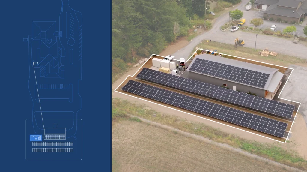
The Orcas Center had limited space to work with, and wanted to colocate all microgrid equipment at the south end of the property for ease of installation and maintenance. Local zoning ordinance required an extended 20 ft setback from adjacent property lines, and the desired equipment area was surrounded with trees and shrubs, which presented a fire hazard. We ended up clearing vegetation and following equipment spacing requirements to size and locate the pad – maximizing the amount of available space for equipment while satisfying the fire marshal.
Best practice here is, as always, to work closely with your AHJ and fire marshal to determine their BESS size and setback requirements. If you’re looking to brush up on fire code, consider registering for one of our self-paced online courses or check out our free Code Corner series on YouTube.

Working with Mayfield Renewables as Engineer of Record on the Orcas Center project was a true partnership. Their team brought deep technical rigor, clear communication, and a pragmatic understanding of how microgrids actually get built in the real world. They were thoughtful collaborators throughout design, responsive to evolving constraints, and aligned with our shared goal of delivering a resilient, community-centered energy system. It was exactly the kind of EOR relationship you hope for on a complex project like this.
Markus Virta
Co-Founder & Managing Partner of Cascadia Renewables
Result
Today, Orcas Center’s microgrid is fully operational. Solar, energy storage, and generator resources work in concert to power the facility during both grid-connected and islanded scenarios. Toggle through the carousel on the right to see how the microgrid operates under different grid, solar, and energy storage conditions.
The microgrid system will offset an estimated 87% of the Orcas Center’s annual electricity demand, greatly reducing reliance on the bulk power system and enabling upwards of 56 hours of resilience performance in the darker winter months and near-continuous islanded operation in the solar-rich summer months.
The ELM energy storage system also enabled value stacking, going beyond resilience to provide demand charge reduction and energy arbitrage when connected to the grid.
The Orcas Center project underscores the importance of performing early-stage feasibility analysis and working directly with community stakeholders to define project goals. We are grateful to work with experienced and passionate partners such as Cascadia Renewables that develop high-impact, community-led projects. While no two microgrids are the same, the lessons learned from the Orcas Center project can be applied to other community resilience hubs across the U.S.