Technical Article
How to Calculate PV String Size
Click here for the 2023 Update: How to Calculate PV String Size
When designing a solar PV system it’s critical to know the minimum and maximum number of PV modules that can be connected in series, referred to as a string. PV modules produce more voltage in low temperatures and less voltage in high temperatures. If too many modules are on the same string then the maximum input voltage of the inverter may be exceeded and the electrical equipment connected to that string could be damaged, or worse, start a fire. If too few modules are on the same string, then the inverter might shutoff when the outside temperature is high and the system will underperform during the summer months.
Use the Mayfield Design Tool
The easiest and fastest way to calculate PV string size and voltage drop is to use the Mayfield Design Tool. Our web-based calculator has data for hundreds of PV modules, inverters, and locations so you don’t have to look up datasheets nor do manual calculations. You can access the Mayfield Design Tool for free on our website here.
Manual String Size Calculations
How to Calculate Minimum String Size
The minimum string size is the minimum number of PV modules, connected in series, required to keep the inverter running during hot summer months. The National Electrical Code (NEC) doesn’t address the effects of high temperatures on module voltages because that is considered a performance issue, not a safety issue. However, our customers care whether the system we design is operating during the summertime when their return on investment is highest.
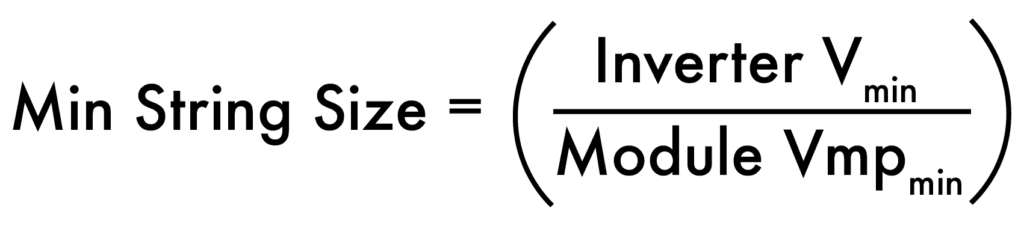
In order to calculate the minimum string size we first have to calculate the minimum output voltage, Module Vmp_min, that each module will produce for the specific installation site. Then take the inverter minimum voltage and divide by the calculated module minimum voltage to get the minimum number of modules.
The module minimum voltage is calculated using the high temperature for the installation site when the modules would produce the lowest expected voltage. This is because as a PV module gets hotter it is less efficient and produces less voltage.

Where:
Module Vmp_min = minimum module voltage expected at site high temperature [V].
Vmp = rated module max power voltage [V]. Found on the module data sheet.
Tmax = the ambient high temperature for the installation site [°C].
The industry standard for site temperature data is provided by the American Society of Heating, Refrigerating and Air-Conditioning Engineers (ASHRAE). Find ASHRAE site temperature data for free on Solar ABCs.
There are three different options for Tmax, all are acceptable for design best practices:
-
2% ASHRAE high temperature (most commonly used)
-
0.4% ASHRAE high temperature (required for ETO incentives, slightly more conservative)
-
highest temperature ever recorded (most conservative)
Tadd = temperature adjustment for installation method [°C].
The temperature is adjusted to take into account the installation method. In general, roof mounted systems get hotter than ground mounted systems because there is typically less airflow and the roof surface radiates heat.
-
Roof mounted, parallel to roof (<6 in. standoff): +35°C
-
Roof mounted, rack-type mount (>6 in. standoff): +30°C
-
Ground or pole mounted: +25°C
T_STC = temperature at standard test conditions, 25°C
Tk_Vmp = module temperature coefficient of Vmp [%/°C], always expressed as a negative value. Found on the module datasheet.
This is not the same as the temperature coefficient for Voc. Most often the temperature coefficient of Vmp isn’t on the module datasheet. You can use the power temperature coefficient instead since this will be almost the same.
Where:
Module Vmp_min = minimum module voltage expected at site high temperature [V], from the previous calculation above.
Inverter Vmin = the inverter minimum MPPT voltage [V].
-
Using the inverter minimum operating voltage will ensure that the inverter will keep running, however, the Max Power Point Tracking (MPPT) function of the inverter may stop working. This is the function that ensures the inverter is producing the maximum possible power output at any given time.
-
Using the inverter minimum MPPT voltage will ensure that the inverter is running and the MPPT function is working properly, giving the highest possible performance.
The calculated minimum number of modules in a string must always be rounded up to the next whole number so that the minimum inverter voltage is being met.
Example
Let’s assume we’re designing a PV system in Corvallis, OR that is roof-mounted, parallel to the roof (<6in. standoff) using SunPower P17 350W (SPR-P17-350-COM-1000V) modules and CPS 60kW, 1000V string inverters.
From the module datasheet
Vmp = 43.1 V
Tk_Vmp = -0.37 %/°C
T_STC = 25°C
From the inverter datasheet
Inverter Vmin (MPPT) = 540 V
From SolarABCs website and based on the site location
Tmax (2% ASHREA) = 33°C
Based on the mounting type, Tadd = 35°C
First, we will calculate Module Vmp_min:
Module Vmp_min = Vmp x [1+ ((Tmax + Tadd - TSTC) x (Tk_Vmp/100))]
= 43.1V x [1+ ((33°C + 35°C - 25°C) x (-0.37%/°C / 100))]
= 43.1V x [1+ ((43°C) x (-0.0037/°C))]
= 43.1V x [1+ (-0.1591)]
=43.1V x [0.8409]
= 36.24 V
This calculation shows you that the minimum module voltage expected at this site's high temperature is about 84% of the rated module Vmp.
Next, we will calculate the minimum string size:
Min String Size = Vmin_inverter / Module Vmp_min
= 540V/36.24V
= 14.89
Lastly, we will round up to the nearest whole number:
Min String Size = 15 modules
How to Calculate Maximum String Size
The maximum string size is the maximum number of PV modules that can be connected in series and maintain a maximum PV voltage below the maximum allowed input voltage of the inverter. This is considered a safety concern and is addressed by NEC 690.7(A) Photovoltaic Source and Output Circuits. The 2017 NEC allows the following three methods for this calculation.
-
Using the module open-circuit voltage temperature coefficient and the lowest expected ambient temperature to correct the PV module rated open-circuit voltage. (The method used in this article).
-
For crystalline and muticrystalline modules, using the correction factors in NEC Table 690.7(A) and the lowest expected ambient temperature. This is the most conservative method.
-
For PV systems 100kWac or greater, using an industry-standard method provided by a licensed professional electrical engineer.
Using the first method allowed by the NEC, the Module Voc_max is calculated using the site lowest expected ambient temperature when the modules would produce the highest expected voltage.

Where:
Module Voc_max = maximum module voltage corrected for the site lowest expected ambient temperature [V].
Voc = module rated open current voltage [V]. Found on module data sheet.
Tmin = lowest expected ambient temperature for site [°C].
The key word here is “expected”. For many designers, using the data provided by ASHRAE for the Extreme Annual Mean Minimum Design Dry Bulb Temperature is the answer in this scenario and is recommended by the NEC. You can also consider using the lowest recorded temperature, this is the more conservative approach. Either temperature value can be justified and will result in proper system design. Find site temperature data on Solar ABCs.
T_STC = temperature at standard test conditions, 25°C.
Tk_Voc = module open current voltage temperature coefficient [%/°C], always expressed as a negative value. Found on module data sheet.
Where:
Module Voc_max = maximum module voltage corrected for the site lowest expected ambient temperature [V] from previous calculation above.
Inverter Vmax = the inverter maximum allowable voltage [V]. Found on inverter data sheet.
The calculated maximum number of modules in a string must always be rounded down to the next whole number so that the maximum inverter voltage is not exceeded.
Example
Let’s assume we’re designing a PV system in Corvallis, OR that is roof mounted, parallel to the roof (<6in. standoff) using SunPower P17 350W (SPR-P17-350-COM-1000V) modules and CPS 60kW, 1000V string inverters.
From the module datasheet
Voc = 51.7 V
Tk_Voc = -0.34 %/°C
Note: The datasheet shows Tk_Voc = -175.8 mV/°C. You can convert this to a percentage -0.1758 V / 51.7 V = -0.0034 = -0.34%
T_STC = 25 °C
From the inverter datasheet
Inverter Vmax = 1000 V
From SolarABCs website and based on the site location
Tmin = -8 °C
First, we will calculate the Module Voc_max:
Module Voc_max = Voc x [1 + (Tmin - TSTC) x (Tk_Voc/100)
= 51.7V x [1 + (-8°C - 25°C) x (-0.34 %/°C /100)]
= 51.7V x [1 + (-33°C) x (-0.0034/°C)]
= 51.7V x [1 + (0.1122)]
= 51.7V x [1.1122]
= 57.50 V
This calculation shows you that the maximum module voltage expected at this site low temperature is about 11% higher than the rated module Voc.
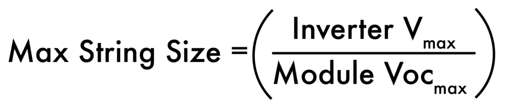
Next, we will calculate the maximum string size:
Max String Size = Inverter Vmax / Module Voc_max
= 1000 V / 57.50 V
= 17.39
Lastly, we will round down to the nearest whole number:
Max String Size = 17 modules
Max Voltage for PV Systems 100kW(AC) or Greater
The 2017 NEC added a third method for calculating maximum voltage and allows using an “industry-standard method” provided by a licensed professional electrical engineer. This method requires a more in-depth analysis of the site-specific weather data such as irradiance and the temperatures during sunlight hours when the PV system is actually operating. The amount of work required to do this analysis may not be worth the additional cost for smaller systems but may be very valuable for large PV systems.
See Resources & References below for the links to the Sandia report referenced in the NEC as an industry-standard method and the article Simulating NEC Voltage and Current Values which explains this method and gives a detailed example.
Multiple Allowable String Sizes
For the example above, the allowable string size is between 15 to 17 modules. That means that we have the flexibility of choosing 15, 16 or 17 modules connected in series on one string. Depending on the available installation space and system layout we might need to use a mix of string sizes. When using multiple string sizes we want to make sure that all the strings going into one MPPT have the same number of modules. Having multiple string sizes connected to the same MPPT is one cause of mismatch, the variation of input power from one string to another. Mismatch affects the MPPT’s ability to function properly and will result in decreased inverter performance.
For example, the CPS 60kW string inverter has 15 inputs and 3 MPPTs allowing for 5 strings to be connected to each MPPT. Let’s assume we’re using 5 strings of 15 modules, 5 strings of 16 modules, and 5 strings of 17 modules all connected to the same inverter. All the strings with 15 modules should be connected to MPPT 1, all the strings with 16 modules should be connected to MPPT 2, and all the strings with 17 modules should be connected to MPPT 3.
Every inverter manufacturer has a team of applications engineers who can help you determine proper system design with their products. If you’re ever unsure of what string sizes to use with a particular inverter you can contact the technical support team for the inverter manufacturer.
Resources & References
Free String Sizing Tools
-
The Mayfield Design Tool for string size and voltage drop calculations.
-
PVselect.com a free solar design tool provided by Blue Oak Energy and SolarPro magazine.
-
Most inverter manufacturers have their own string sizing tool for their products that can be found on their website.
Useful Resources
-
Solar ABCs has ASHREA site temperatures by zip code in United States.
-
Solar Design Temps has site temperatures worldwide.
-
National Electrical Code (NEC), NFPA 70, National Fire Protection Association
-
Climatic Design Information, Chapter 14 from the 2017 ASHRAE Handbook—Fundamentals.
-
PV Performance Modeling Collaborative (PVPMC) provides detailed information and resources on PV system modeling that meets NEC 690.7(A)(3).
-
System Advisor Model (SAM) is a free performance modeling tool provided by National Renewable Energy Laboratory (NREL)
Additional Reading
-
“String Theory: PV Array Voltage Calculations” by Ryan Mayfield, Home Power Magazine Issue #125, June / July 2008.
-
“METHODS: Selecting Appropriate PV Array String Sizes” by Kent Osterberg, Home Power Magazine Issue #173, May / June 2016.
-
“Install tip: Know How Inverter MPPT Functionality Affects Performance” by David Bromberg, Aurora Solar via Solar Power World.
-
“Understanding PV System Losses, Part 1: Nameplate, Mismatch, and LID Losses” by Andrew Gong, Aurora Solar blog.
-
“Array Voltage Considerations” by Bill Brooks, SolarPro Magazine Issue 3.6, Oct/Nov ‘10
-
“Simulating NEC Voltage and Current Values” by Charles Ladd, SolarPro Magazine Issue 11.4, July/August 2018.
-
Photovoltaic Array Performance Model, SAND 2004-3535, Sandia National Labratories. Referenced in 2017 NEC, industry standard method for calculating maximum voltage of a PV system.
Have Questions or Comments?
Comment below or email design@mayfield.energy and we would be happy to answer. Feedback welcome!

