Technical Article
AC vs. DC Coupling Energy Storage Systems
At Mayfield Renewables, we routinely design and consult on complex solar-plus-storage projects. In this article, we outline the relative advantages and disadvantages of two common solar-plus-storage system architectures: ac-coupled and dc-coupled energy storage systems (ESS).
Before jumping into each solar-plus-storage system, let’s first define what exactly a typical grid-tied interactive PV system and an “energy storage system” are.
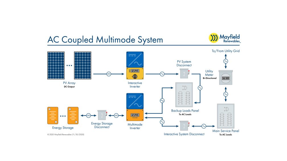
Looking at the diagram below, a simplified interactive PV system is composed of a dc power source (PV modules), a power converter to convert from dc to ac (interactive inverter), and ac loads (main service panel).
When the sun is shining, the PV modules produce dc power which is fed through the interactive inverter which then feeds the main service panel. The interactive inverter “interacts” with the grid to send excess power to the utility and also will shut down during a power outage. This prevents the PV modules from producing power which could energize downed power lines.
Now that we have a simple grid-tied system, let’s build onto it by adding energy storage. Article 706.2 of the 2017 National Electrical Code (NEC) defines an energy storage system as: “One or more components assembled together capable of storing energy for use at a future time. ESS(s) can include but is not limited to batteries, capacitors, and kinetic energy devices (e.g., flywheels and compressed air). These systems can have ac or dc output for utilization and can include inverters and converters to change stored energy into electrical energy.”
For the purposes of our analysis, we loosely define ESS as a component(s) of our circuit designed to store energy for later use (e.g., a lead-acid or lithium-ion battery bank).
AC-Coupled Systems
As mentioned above, PV modules will produce dc power. That power must be converted to ac to be used in most commercial and residential applications. In contrast, battery cells must be charged with dc and will output dc power. The ac-dc distinction has major system design implications.
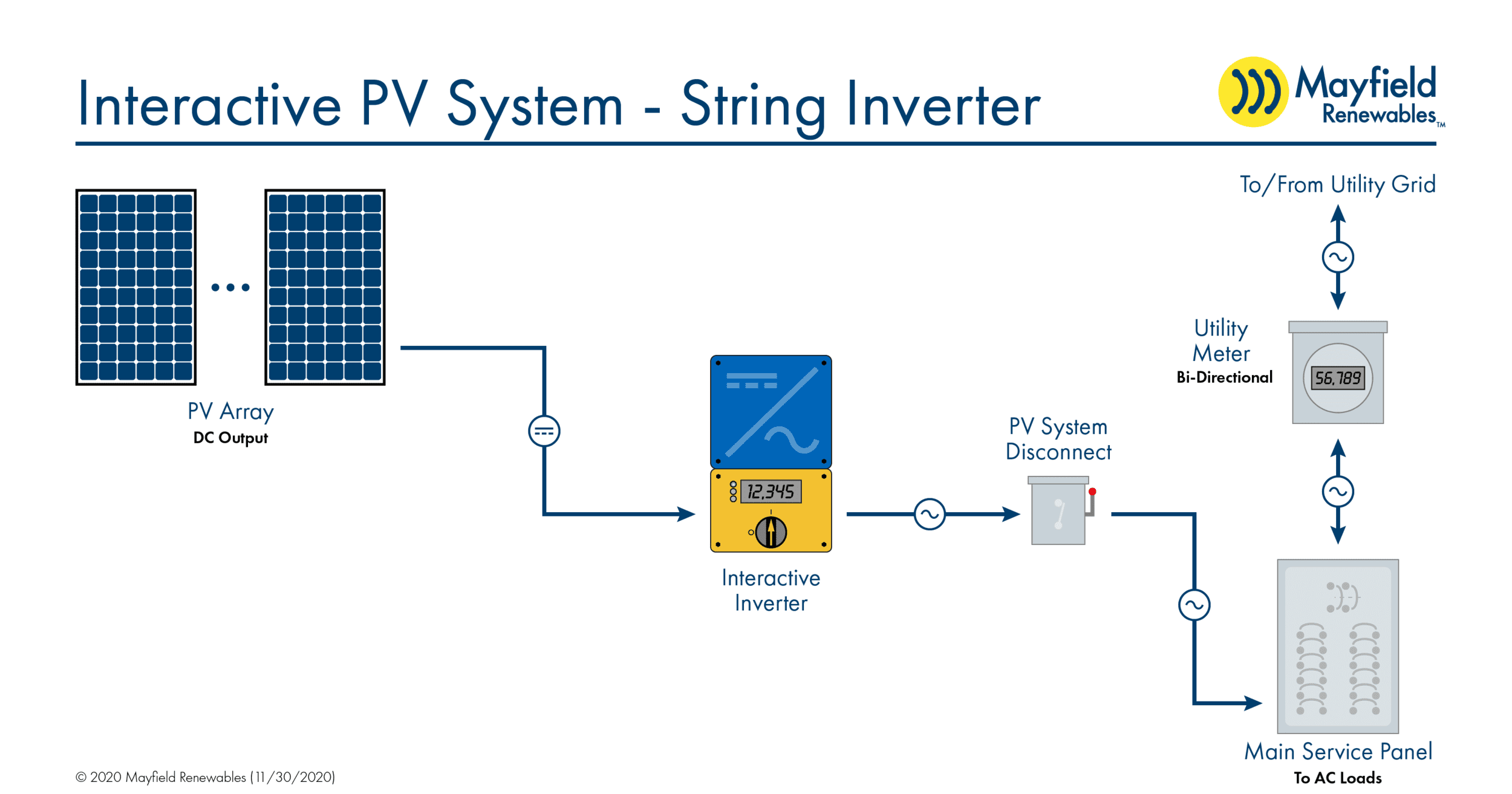
In an ac-coupled system, power from the PV modules is converted to ac prior to connecting to the ESS. In other words, the output from the PV modules is fed through an interactive inverter before it reaches the ESS. This means that the power must be converted to dc before charging the ESS, and any power output from the ESS must be converted once again to ac. To achieve this, an additional multimode inverter is required.
Moving from left to right in the diagram above: The PV array produces dc power, which is immediately converted to ac by the interactive inverter. That power feeds a backup loads panel containing select loads formerly located in the main service panel. The backup panel is also connected to the ESS, with a multimode inverter acting as a middleman to convert ac to dc when the ESS is charging, and dc to ac when discharging.
In this setup, it’s possible for the PV array, backup loads panel, and ESS to operate independently from the grid. During a power outage, the multimode inverter—using power from the ESS—will mimic signals from the grid, allowing the interactive inverter to stay online and the PV array to continue producing power to feed the backup loads panel and charge the ESS with any excess power.
DC-Coupled Systems
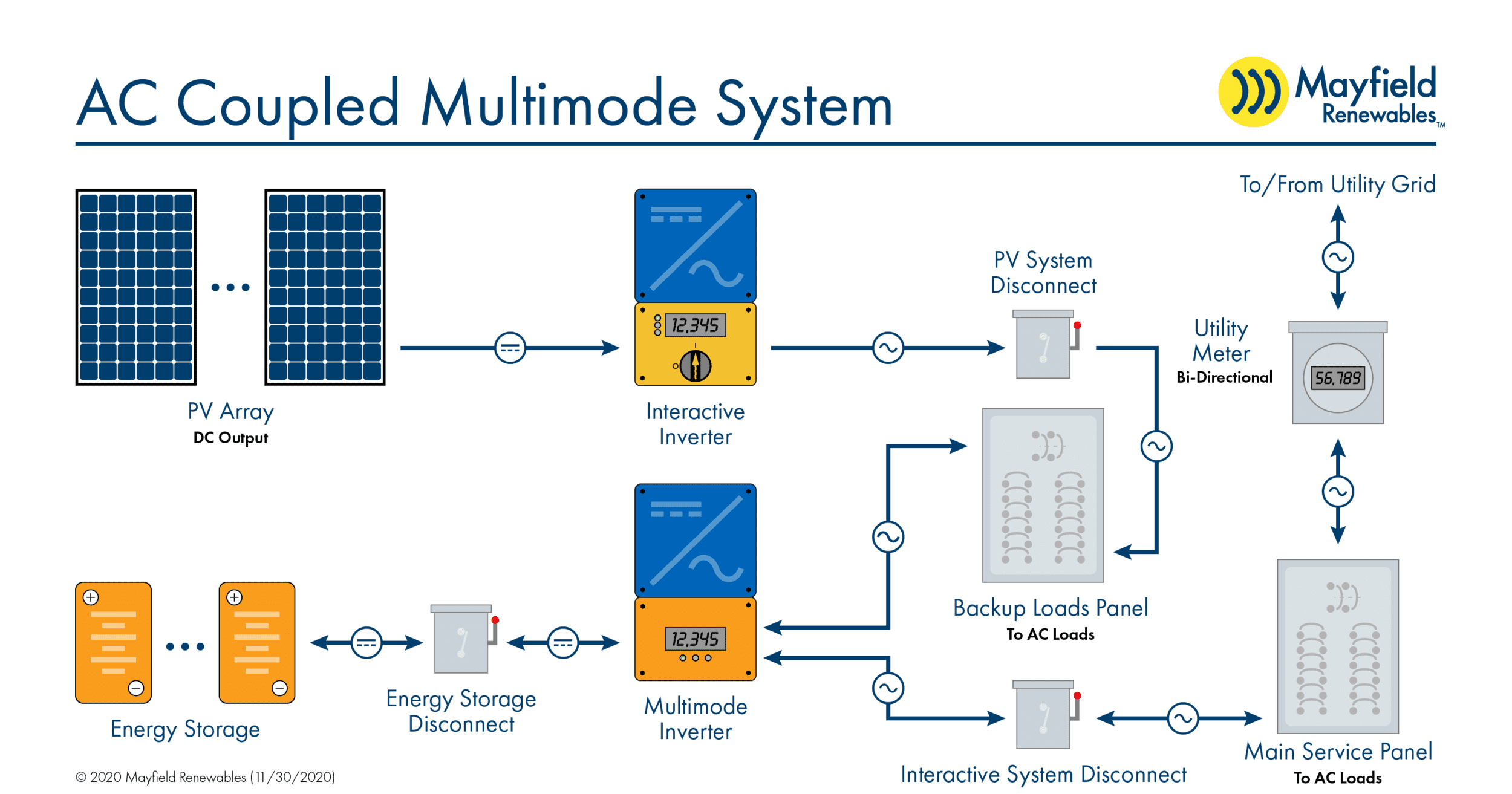
DC-coupled systems rely only on a single multimode inverter that is fed by both the PV array and ESS. With this system architecture, dc output power from the PV modules can directly charge the ESS. No dc-to-ac conversion is required between the PV array and ESS.
The backup loads panel and main service panel—both of which require ac power—are placed downstream from the multimode inverter. In the case of a power outage, the microgrid interconnect device (which is commonly integrated into the multimode inverter) will cut off the multimode inverter’s output to the main service panel but the inverter will continue to supply ac power to the backup loads panel.
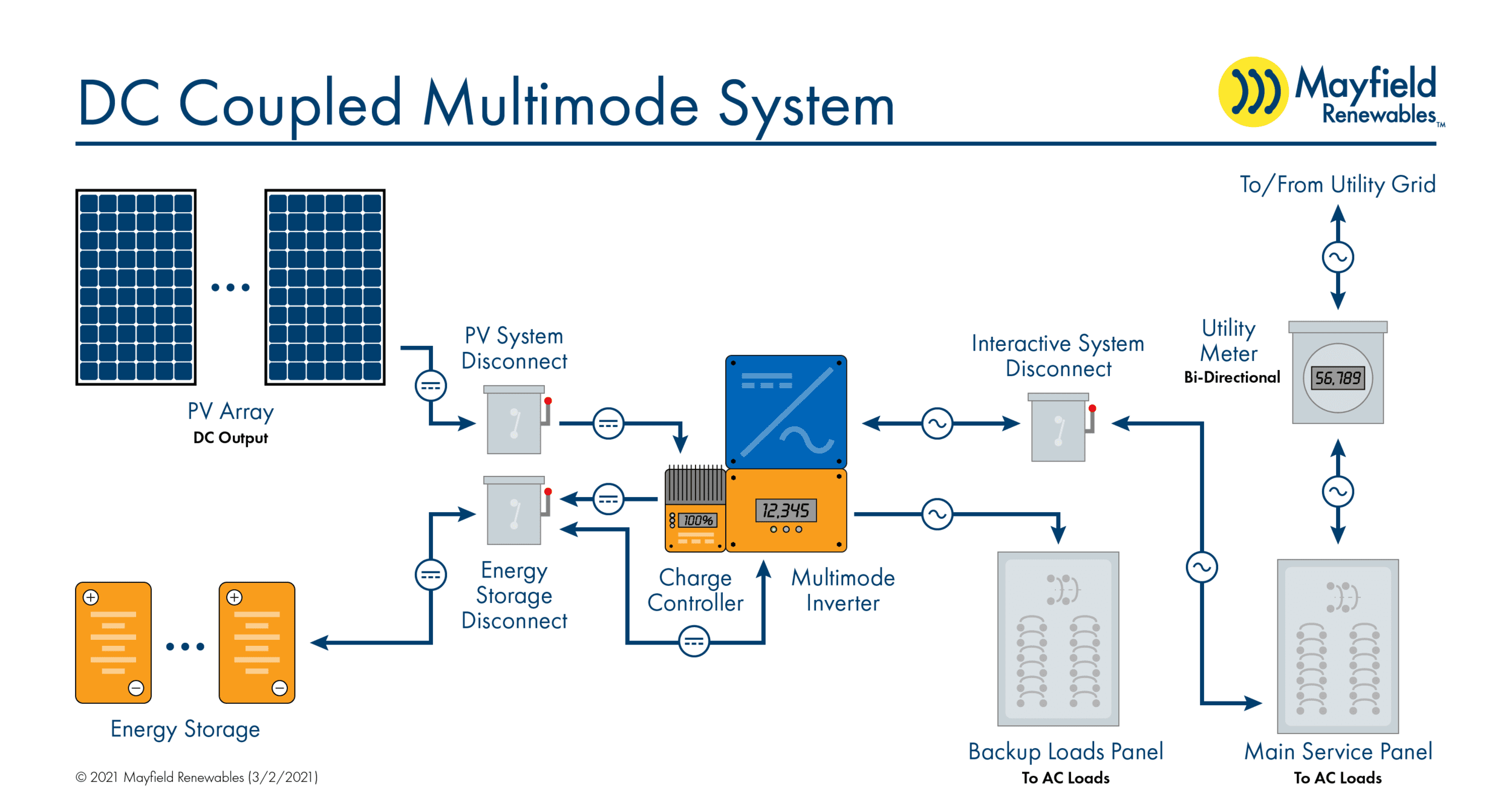
Moving from left to right in the diagram above: The PV array outputs dc power to the ESS and the multimode inverter. The multimode inverter will convert the dc power to ac and any power in excess of the loads in the backup and main service panels (or that is used to charge the ESS) is exported to the grid.
Advantages of AC Coupling
Retrofits
Adding an ESS to an existing grid-tied interactive PV system is not uncommon. Doing so can cause headaches for system designers, and the easiest solution is often ac coupling the new ESS.
Compare the simple interactive PV system and the ac-coupled system above. Note that in both cases, the PV side of the system is the same. AC coupling will add a backup loads panel and multimode inverter but, crucially, the existing PV system does not need to be redesigned.
Higher Inverter Capacity
A dc-coupled system relies on only a single multimode inverter and is thus limited by its capacity. AC-coupled systems have two inverters (one interactive and one multimode), both of which feed the backup loads panel. So if an outage occurs while the sun is still shining, the backup loads panel can have the kW capacity of both inverters available.
Redundancy
As with any electrical system, PV designers should consider potential points of failure. In an ac-coupled system, if the battery-based multimode inverter is disabled, a simple bypass switch will keep the PV array and interactive inverter online (as long as the grid is up). This is not the case for dc-coupled systems, which are reliant on a single multimode inverter at the heart of the system architecture.
Efficiency
Interactive inverters tend to be more efficient than multimode inverters. If the sun is shining and the power being produced is consumed immediately (i.e., the power output from the PV array is directly feeding the loads rather than passing through the multimode inverter to charge the ESS) an ac-coupled system architecture will be more efficient than its dc counterpart.
Advantages of DC Coupling
Efficiency
While an ac-coupled system is more efficient when the PV array is feeding loads directly, a dc-coupled system is more efficient when power is routed through the ESS (e.g., when the ESS is charged directly and discharged at a later time) since there is only one conversion from dc to ac—a single inverter, rather than two, to pass through.
Full PV Array Power
In typical interactive and ac-coupled systems, inverters are downsized under the assumption that the PV array will rarely, if ever, produce at its nominal rating. For example, consider a 5kW PV array that is tied to a 4kW interactive inverter. This hypothetical system is now limited to a nominal 4kW power output.
For dc-coupled systems, the power feeding the ESS is not limited by an interactive inverter. Returning to the hypothetical system above, but without the interactive inverter this time, a theoretical maximum of about 5kW could be used to charge the ESS and/or feed the multimode inverter without any power limiting.
Direct Charging
Low-battery-voltage situations can arise within ac-coupled systems. If too much energy is pulled out of the battery bank during an outage, that energy can cascade throughout the system, shutting down the multimode inverter, then the interactive inverter and the PV array. Since there is no way for the PV array to directly charge the batteries in this case, system owners may have to wait for grid power to return before the system can come back online.
Conversely, a dc-coupled system can continuously send power (during daylight hours) directly from the PV array to the ESS. The unencumbered pathway between the PV array and battery bank allows the battery voltage to rise and thus the multimode inverter can turn back on and supply power to the backed-up loads without having to wait for the grid power to return.

